Mitsubishi 380. Manual - part 822


  Index      Mitsubishi     Mitsubishi 380 - service repair manual 2005 year


Search            


Content   ..  820  821  822  823   ..


Mitsubishi 380. Manual - part 822


SRS AIR BAG DIAGNOSIS

SUPPLEMENTAL RESTRAINT SYSTEM (SRS)

52B-212

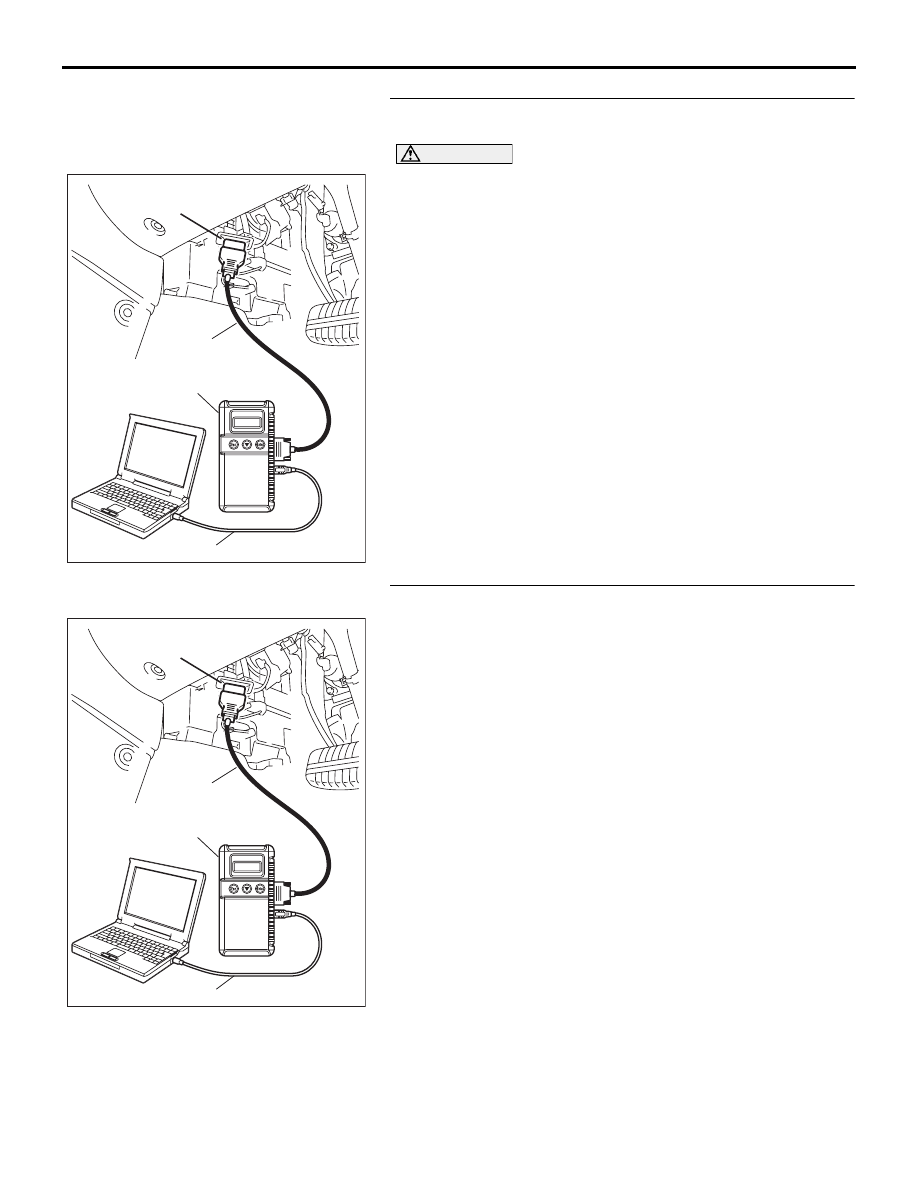
STEP 3. Using diagnostic tool MB991958, read the 
diagnostic trouble code.

CAUTION

To prevent damage to diagnostic tool MB991958, always 
turn the ignition switch to the "LOCK" (OFF) position 
before connecting or disconnecting diagnostic tool 
MB991958.
Check that the DTC except B1547 is set.
(1) Turn the ignition switch to the "ON" position.
(2) Check if the DTC is set.
(3) Turn the ignition switch to the "LOOK (OFF)" position.

Q: Is the DTC set?

YES : Carry out the troubleshooting according to a set DTC. 

Refer to 

P.52B-21

.

NO :  Go to Step 4.

STEP 4. Recheck for diagnostic trouble code.
Check again if the DTC is set.
(1) Erase the DTC.
(2) Turn the ignition switch to the "ON" position.
(3) Check if the DTC is set.
(4) Turn the ignition switch to the "LOCK" (OFF) position.

Q: Is DTC B1547 set?

YES : Replace the SRS-ECU (Refer to 

P.52B-234

).

NO :  The procedure is complete.

00DB076A

MB991910

DATA LINK

CONNECTOR

MB991824

MB991827

00DB076A

MB991910

DATA LINK

CONNECTOR

MB991824

MB991827

SRS AIR BAG DIAGNOSIS

SUPPLEMENTAL RESTRAINT SYSTEM (SRS)

52B-213

DTC U1073: Bus Off

CAUTION

If DTC U1073 is set in the SRS-ECU, diagnose the 
CAN main bus line.

CAUTION

Whenever the ECU is replaced, ensure that the 
communication circuit is normal.

.

TROUBLE JUDGMENT

DTC U1073 will be stored when the SRS-ECU 
ceases CAN communication (bus off) and then 
resumes the communication when the ignition switch 
is turned to the "LOCK" (OFF) position.

.

TECHNICAL DESCRIPTION (COMMENT) 

The wiring harness wire or connectors may have 
loose, corroded, or damage terminals, or terminals 
pushed back in the connector, or the SRS-ECU may 
be defective.

.

TROUBLESHOOTING HINTS

• Defective connector(s) or wiring harness

• Malfunction of the SRS-ECU

• Refer to circuit diagrams GROUP-

90

• Refer to configuration diagrams GROUP-

80

DIAGNOSIS

Required Special Tools:

•  MB991958: diagnostic tool (MUT-III Sub Assembly)

• MB991824: Vehicle Communication Interface (V.C.I.)

• MB991827: MUT-III USB Cable

• MB991910: MUT-III Main Harness A (Vehicles with CAN 

communication system)

SRS AIR BAG DIAGNOSIS

SUPPLEMENTAL RESTRAINT SYSTEM (SRS)

52B-214

STEP 1. Using diagnostic tool MB991958, diagnose the 
CAN bus line.

CAUTION

To prevent damage to diagnostic tool (MUT-III), always turn 
the ignition switch to the "LOCK" (OFF) position before 
connecting or disconnecting diagnostic tool (MUT-III).
(1) Connect diagnostic tool MB991958 to the data link 

connector.

(2) Turn the ignition switch to the "ON" position.
(3) Diagnose the CAN bus line.
(4) Turn the ignition switch to the "LOCK" (OFF) position.

Q: Is the CAN bus line found to be normal?

YES : Go to Step 2.
NO :  Repair the CAN bus lines (Refer to GROUP 54C, 

precautions on how to repair the can bus lines ).

STEP 2. Recheck for diagnostic trouble code.
Check again if the DTC is set.
(1) Connect diagnostic tool MB991958 to the data link 

connector

(2) Turn the ignition switch to the "ON" position.
(3) Check if the DTC is set.
(4) Turn the ignition switch to the "LOCK" (OFF) position.

Q: Is the check result satisfactory?

YES : There is an intermittent malfunction such as poor 

engaged connector(s) or open circuit (Refer to 
GROUP 00, How to Use Troubleshooting/Inspection 
Service Points 

− How to Cope with Intermittent 

Malfunctions ).

NO :  Replace the A/C-ECU. On completion, check that the 

DTC is not reset.

00DB076A

MB991910

DATA LINK

CONNECTOR

MB991824

MB991827

00DB076A

MB991910

DATA LINK

CONNECTOR

MB991824

MB991827

SRS AIR BAG DIAGNOSIS

SUPPLEMENTAL RESTRAINT SYSTEM (SRS)

52B-215

TROUBLE SYMPTOM CHART

M1524003400495

CAUTION

During diagnosis, a DTC code associated with 
another system may be set when the ignition 
switch is turned on with connector(s) discon-
nected. After completing the repair, confirm all 
systems for DTC code(s). If DTC code(s) are set, 
erase them all.

SYMPTOM

INSPECTION PROCEDURE NO. REFERENCE PAGE

Communication between the diagnostic tool 
and the SRS-ECU is not possible.

1

P.52B-216

Power supply circuit system

2

P.52B-217

When the ignition key is turned to the "ON" 
position (engine stopped), the SRS warning 
light does not illuminate.

3

P.52B-220

After the ignition key is turned to the "ON" 
position, the SRS warning light does not go off 
within approximately seven seconds.

4

P.52B-220


Content   ..  820  821  822  823   ..