Mitsubishi 380. Manual - part 821


  Index      Mitsubishi     Mitsubishi 380 - service repair manual 2005 year


Search            


Content   ..  819  820  821  822   ..


Mitsubishi 380. Manual - part 821


SRS AIR BAG DIAGNOSIS

SUPPLEMENTAL RESTRAINT SYSTEM (SRS)

52B-208

STEP 2. Recheck for diagnostic trouble code.
Check again if the DTC is set.
(1) Erase the DTC.
(2) Turn the ignition switch to "ON" position.
(3) Check if the DTC is set.
(4) Turn the ignition switch to the "LOCK" (OFF) position.

Q: Is the DTC set?

YES : Go to Step 3
NO :  There is an intermittent malfunction such as poor 

engaged connector(s) or open circuit (Refer to 
GROUP 00, How to Use Troubleshooting/Inspection 
Service Points 

− How to Cope with Intermittent 

Malfunctions ).

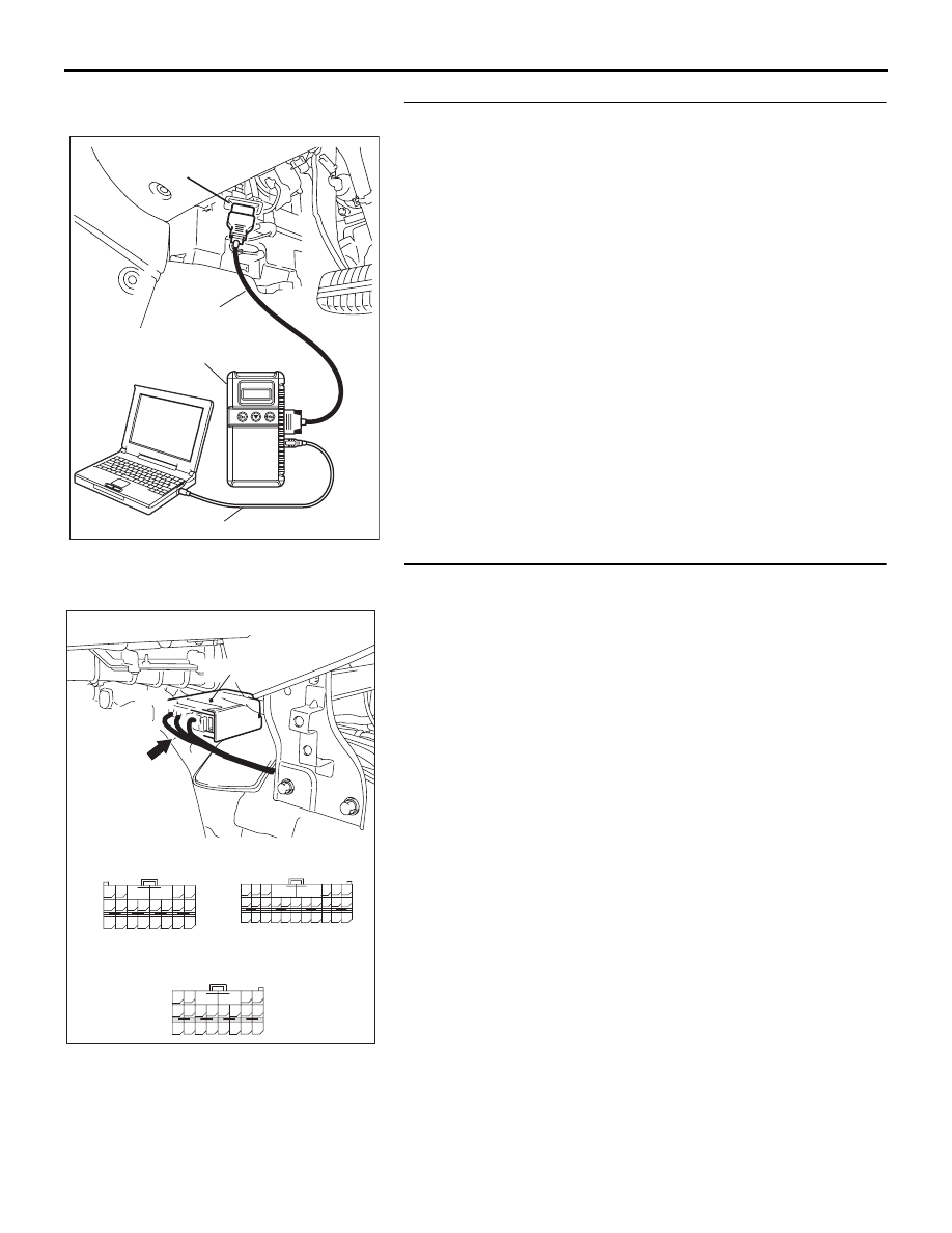
STEP 3. Check the SRS-ECU connector D-26, C-121 and 
D-27.
Q: Are connectors correctly engaged?

YES : Go to Step 4.
NO :  Engage the connectors correctly. Then go to Step 5.

00DB076A

MB991910

DATA LINK

CONNECTOR

MB991824

MB991827

24DB065A

63

55

51

69

61

66

58

65

64

5657

68

60

67

59

70

62

53

52 B A

54

42

31

38

27

21

41

28

39

22

30

25

47

36

33

44

34

45

37

48

26

29

23

40

32

43

35

46

24

B

A

A

B

18

10

15

7

13

5

14

6

16

8

17

9

19

11

20

12

1 2

3 4

SRS-ECU

D-26 Floor harness

side connector

(rear view)

D-27 Floor harness

side connector 

(rear view)

D-26    (Y),

C-121  (Y),

D-27    (Y)

CONNECTORS:  D-26, C-121, D-27

C-121 Instrument harness

connector (rear view)

SRS AIR BAG DIAGNOSIS

SUPPLEMENTAL RESTRAINT SYSTEM (SRS)

52B-209

STEP 4. Check SRS-ECU connector D-26, C-121 and D-27 
for damage.
(1) Disconnect SRS-ECU connectors D-26, C-121 and D-27.
(2) Check the connector lock switch terminal inside the harness 

side connector for improper contact or deformation.

Q: Are the SRS-ECU connector D-26, C-121 and D-27 in 

good condition? 
YES : 
Erase the diagnostic trouble code memory, and check 

the diagnostic trouble code. If DTC B1519 sets, 
replace the SRS-ECU (Refer to 

P.52B-234

). Then go 

to Step 5.

NO :  Replace the SRS-ECU connector D-26, C-121 and 

D-27. Refer to GROUP 00E, Harness Connector 
Inspection . Then go to Step 5.

AC307924 AB

SRS-ECU HARNESS SIDE 
CONNECTOR (FRONT VIEW)

CONNECTOR LOCK
SWITCH TERMINAL

24DB065A

63

55

51

69

61

66

58

65

64

5657

68

60

67

59

70

62

53

52 B A

54

42

31

38

27

21

41

28

39

22

30

25

47

36

33

44

34

45

37

48

26

29

23

40

32

43

35

46

24

B

A

A

B

18

10

15

7

13

5

14

6

16

8

17

9

19

11

20

12

1 2

3 4

SRS-ECU

D-26 Floor harness

side connector

(rear view)

D-27 Floor harness

side connector 

(rear view)

D-26    (Y),

C-121  (Y),

D-27    (Y)

CONNECTORS:  D-26, C-121, D-27

C-121 Instrument harness

connector (rear view)

SRS AIR BAG DIAGNOSIS

SUPPLEMENTAL RESTRAINT SYSTEM (SRS)

52B-210

STEP 5. Recheck for diagnostic trouble code. 
Check again if the DTC is set.
(1) Erase the DTC.
(2) Turn the ignition switch to the "ON" position.
(3) Check if the DTC is set.
(4) Turn the ignition switch to the "LOCK" (OFF) position.

Q: Is DTC B1519 set?

YES : Return to Step 1.
NO :  The procedure is complete. 

DTC B1547: Passenger’s Front Air Bag Cut Off System

CAUTION

If DTC B1547 is set in the SRS-ECU, always diag-
nose the CAN main bus line.

.

DTC SET CONDITIONS

This DTC is set if the following conditions are 
detected:

• Malfunction of front passenger’s air bag module 

system

• Malfunction of SRS-ECU system

.

TROUBLESHOOTING HINTS

Malfunction of SRS-ECU

• Refer to circuit diagrams GROUP-

90

• Refer to configuration diagrams GROUP-

80

.

DIAGNOSIS

Required Special Tools:

• MB991958: diagnostic tool (MUT-III Sub Assembly)

• MB991824: Vehicle Communication Interface (V.C.I.)

• MB991827: MUT-III USB Cable

• MB991910: MUT-III Main Harness A (Vehicles with CAN 

communication system)

00DB076A

MB991910

DATA LINK

CONNECTOR

MB991824

MB991827

SRS AIR BAG DIAGNOSIS

SUPPLEMENTAL RESTRAINT SYSTEM (SRS)

52B-211

STEP 1. Using diagnostic tool MB991958, diagnose the 
CAN bus line.

CAUTION

To prevent damage to diagnostic tool MB991958, always 
turn the ignition switch to the "LOCK" (OFF) position 
before connecting or disconnecting diagnostic tool 
MB991958.
(1) Connect diagnostic tool MB991958. Refer to "How to 

connect the diagnostic tool 

P.52B-19

."

(2) Turn the ignition switch to the "ON" position.
(3) Diagnose the CAN bus line.
(4) Turn the ignition switch to the "LOCK" (OFF) position.

Q: Is the CAN bus line found to be normal?

YES : Go to Step 2.
NO :  Repair the CAN bus line (Refer to GROUP 54C, 

Diagnosis ).

STEP 2. Recheck for diagnostic trouble code.
Check again if the DTC is set.
(1) Erase the DTC.
(2) Turn the ignition switch to the "ON" position.
(3) Check if the DTC is set.
(4) Turn the ignition switch to the "LOCK" (OFF) position.

Q: Is the DTC set?

YES : Go to Step 3.
NO :  There is an intermittent malfunction such as poor 

engaged connector(s) or open circuit (Refer to 
GROUP 00, How to Use Troubleshooting/Inspection 
Service Points 

− How to Cope with Intermittent 

Malfunctions ).

00DB076A

MB991910

DATA LINK

CONNECTOR

MB991824

MB991827

00DB076A

MB991910

DATA LINK

CONNECTOR

MB991824

MB991827


Content   ..  819  820  821  822   ..