Mitsubishi 380. Manual - part 820
SRS AIR BAG DIAGNOSIS
SUPPLEMENTAL RESTRAINT SYSTEM (SRS)
52B-204
DTC B1499: SRS-ECU Air Bag Condition Monitor Detects Deployed Air Bag
CAUTION
If DTC B1499 is set in the SRS-ECU, always diag-
nose the CAN main bus line.
.
DTC SET CONDITIONS
This DTC is set after the air bag has deployed. If this
DTC is set before the air bag has deployed, the
cause is probably a malfunction inside the
SRS-ECU.
.
TROUBLESHOOTING HINTS
Malfunction of the SRS-ECU
• Refer to circuit diagrams GROUP-
• Refer to configuration diagrams GROUP-
.
DIAGNOSIS
Required Special Tool:
• MB991958: diagnostic tool (MUT-III Sub Assembly)
• MB991824: Vehicle Communication Interface (V.C.I.)
• MB991827: MUT-III USB Cable
• MB991910: MUT-III Main Harness A (Vehicles with CAN
communication system)
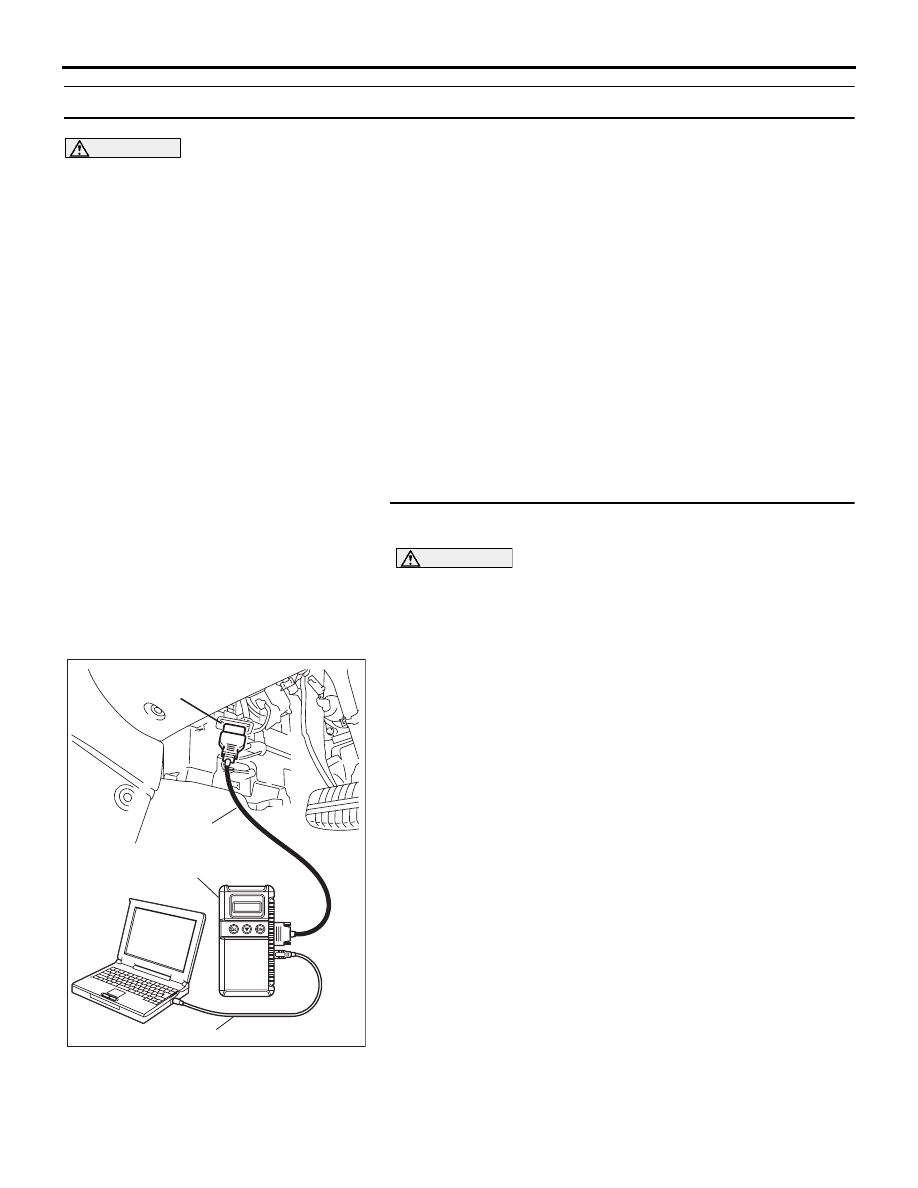
STEP 1. Using diagnostic tool MB991958, diagnose the
CAN bus line.
CAUTION
To prevent damage to diagnostic tool MB991958, always
turn the ignition switch to the "LOCK" (OFF) position
before connecting or disconnecting diagnostic tool
MB991958.
(1) Connect diagnostic tool MB991958. Refer to "How to
connect the diagnostic tool
."
(2) Turn the ignition switch to the "ON" position.
(3) Diagnose the CAN bus line.
(4) Turn the ignition switch to the "LOCK" (OFF) position.
Q: Is the CAN bus line found to be normal?
YES : Go to Step 2.
NO : Repair the CAN bus line (Refer to GROUP 54C,
Diagnosis ).
00DB076A
MB991910
DATA LINK
CONNECTOR
MB991824
MB991827