Mitsubishi 380. Manual - part 818


  Index      Mitsubishi     Mitsubishi 380 - service repair manual 2005 year


Search            


Content   ..  816  817  818  819   ..


Mitsubishi 380. Manual - part 818


SRS AIR BAG DIAGNOSIS

SUPPLEMENTAL RESTRAINT SYSTEM (SRS)

52B-196

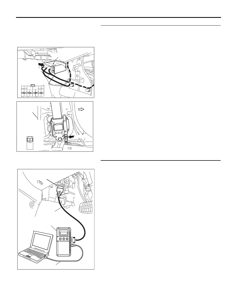
STEP 5. Check harness wires for short circuit to ground 
between SRS-ECU connector D-27 (terminal No.7 and 8) 
and passenger's seat belt pre-tensioner connector D-21 
(terminal No.1 and 2).
Q: Are the harness wires between SRS-ECU connector 

D-27 (terminal No.7 and 8) and passenger's seat belt 
pre-tensioner connector D-21 (terminal No.1 and 2) in 
good condition?
YES : 
Go to Step 6.
NO :  Replace the harness wires between SRS-ECU 

connector D-27 and passenger's seat belt 
pre-tensioner connector D-26. Then go to Step 6.

STEP 6. Recheck for diagnostic trouble code. 
Check again if the DTC is set.
(1) Erase the DTC.
(2) Turn the ignition switch to the "ON" position.
(3) Check if the DTC is set.
(4) Turn the ignition switch to the "LOCK" (OFF) position.

Q: Is DTC B1473 set?

YES : Return to Step 1. 
NO :  The procedure is complete. 

AC306920AC

CONNECTOR: D-21

D-21 (B)

FOWARD

CENTER
PILLAR

HARNESS SIDE
CONNECTOR
(FRONT VIEW)

2 1

24DB064A

CONNECTOR: D-27

SRS-ECU

D-27 (Y)

A

B

18

10

15

7

13

5

14

6

16

8

17

9

19

11

20

12

1 2

3 4

D-27 Floor 

harness

connector

(rear view)

00DB076A

MB991910

DATA LINK

CONNECTOR

MB991824

MB991827

SRS AIR BAG DIAGNOSIS

SUPPLEMENTAL RESTRAINT SYSTEM (SRS)

52B-197

DTC B1476: IG1 Power Supply Circuit System (Fuse No.18 Circuit) DTC B1477: IG1 Power Supply 
Circuit System (Fuse No.19 Circuit)

CAUTION

If DTC B1476 <Fuse No.18> or B1477 <Fuse 
No.19> is set in the combination meter, always 
diagnose the CAN bus lines.

.

CIRCUIT OPERATION

• The SRS-ECU is powered from the ignition 

switch (IG1).

• The SRS-ECU power is supplied from two cir-

cuits. Even if one circuit is shut off, the air bag 
can inflate.

.

DTC SET CONDITIONS

This DTC is set if the voltage between the IG1 termi-
nals (fuse No.18 circuit or fuse No.19 circuit) and 
ground is lower than a predetermined value for a 
continuous period of five second or more. However, if 
the vehicle condition returns to normal, DTC number 
B1476 <Fuse No.18> or B1477 <Fuse No.19> will be 
automatically erased, and the SRS warning light will 
switch off.

.

TROUBLESHOOTING HINTS

• Damaged wiring harnesses or connectors

• Malfunction of the SRS-ECU

• Refer to circuit diagrams GROUP-

90

• Refer to configuration diagrams GROUP-

80

.

DIAGNOSIS

Required Special Tools:

•  MB991958: diagnostic tool (MUT-III Sub Assembly)

• MB991824: Vehicle Communication Interface (V.C.I.)

• MB991827: MUT-III USB Cable

• MB991910: MUT-III Main Harness A (Vehicles with CAN 

communication system)

• MB991223 (MB991222): Harness set (Probe)

24DB062A

CONNECTOR: C-121

C-121 (Y)

SRS-ECU

42

31

38

27

21

41

28

39

22

30

25

47

36

33

44

34

45

37

48

26

29

23

40

32

43

35

46

24

B

A

C-121

INSTRUMENT

HARNESS

CONNECTOR

(REAR VIEW)

SRS AIR BAG DIAGNOSIS

SUPPLEMENTAL RESTRAINT SYSTEM (SRS)

52B-198

STEP 1. Using diagnostic tool MB991958, diagnose the 
CAN bus line.

CAUTION

To prevent damage to diagnostic tool MB991958, always 
turn the ignition switch to the "LOCK" (OFF) position 
before connecting or disconnecting diagnostic tool 
MB991958.
(1) Connect diagnostic tool MB991958. Refer to "How to 

connect the diagnostic tool 

P.52B-19

."

(2) Turn the ignition switch to the "ON" position.
(3) Diagnose the CAN bus line.
(4) Turn the ignition switch to the "LOCK" (OFF) position.

Q: Is the CAN bus line found to be normal?

YES : Go to Step 2.
NO :  Repair the CAN bus line (Refer to GROUP 54C, 

Diagnosis ).

STEP 2. Recheck for diagnostic trouble code.
Check again if the DTC is set.
(1) Erase the DTC.
(2) Turn the ignition switch to "ON" position.
(3) Check if the DTC is set.
(4) Turn the ignition switch to the "LOCK" (OFF) position.

Q: Is the DTC set?

YES : Go to Step 3.
NO :  There is an intermittent malfunction such as poor 

engaged connector(s) or open circuit (Refer to 
GROUP 00, How to Use Troubleshooting/Inspection 
Service Points 

− How to Cope with Intermittent 

Malfunctions ).

00DB076A

MB991910

DATA LINK

CONNECTOR

MB991824

MB991827

00DB076A

MB991910

DATA LINK

CONNECTOR

MB991824

MB991827

SRS AIR BAG DIAGNOSIS

SUPPLEMENTAL RESTRAINT SYSTEM (SRS)

52B-199

STEP 3. Check junction block fuse number 18 <DTC 
B1476> or 19 <DTC B1477>.

Q: Is the fuse burned out?

YES : Go to Step 6.
NO :  Go to Step 4.

STEP 4. Check the power supply circuit for open circuit. 
Measure the voltage at SRS-ECU connector C-121.
(1) Disconnect the negative battery terminal.
(2) Disconnect SRS-ECU connector C-121.
(3) Connect the negative battery terminal.
(4) Turn the ignition switch to the "ON" position.

CAUTION

Do not insert a test probe into the terminal from its front 
side directly, as the connector contact pressure may be 
weakened.
(5) Measure the voltage between C-121 harness side 

connector terminal 23 <DTC B1476> or 24 <DTC B1477> 
and body ground.
Voltage should measure 9 volts or more.

Q: Is the measured voltage within the specified range?

YES : Erase the diagnosis connector memory, and check 

the diagnostic trouble code. If DTC B1476 or B1477 
set, replace the SRS-ECU (Refer to 

P.52B-234

). 

Then go to Step 10.

NO :  Go to Step 5.

24DB062A

CONNECTOR: C-121

C-121 (Y)

SRS-ECU

42

31

38

27

21

41

28

39

22

30

25

47

36

33

44

34

45

37

48

26

29

23

40

32

43

35

46

24

B

A

C-121

INSTRUMENT

HARNESS

CONNECTOR

(REAR VIEW)

AC308202

42

31

38

27

21

41

28

39

22

30

25

47

36

33

44

34

45

37

48

26

29

23

40

32

43

35

46

24

B

A

C-121 HARNESS SIDE

CONNECTOR (REAR VIEW)

AB


Content   ..  816  817  818  819   ..