Mitsubishi 380. Manual - part 823


  Index      Mitsubishi     Mitsubishi 380 - service repair manual 2005 year


Search            


Content   ..  821  822  823  824   ..


Mitsubishi 380. Manual - part 823


SRS AIR BAG DIAGNOSIS

SUPPLEMENTAL RESTRAINT SYSTEM (SRS)

52B-216

SYMPTOM PROCEDURES

INSPECTION PROCEDURE 1: Communication between diagnostic tool and the SRS-ECU is not 
possible.

.

TECHNICAL DESCRIPTION (COMMENT)

If the diagnostic tool (MUT-III Sub Assembly) can not 
communicate with the SRS system, the CAN bus 
lines may be defective. If the SRS system does not 
work, the SRS-ECU or its power supply circuit may 
be defective. 

.

TROUBLESHOOTING HINTS (The most 
likely causes for this case:)

• Damaged wiring harness or connector

• Malfunction of the SRS-ECU

• Refer to circuit diagrams GROUP-

90

• Refer to configuration diagrams GROUP-

80

.

DIAGNOSIS

Required Special Tools:

• MB991958: diagnostic tool (MUT-III Sub Assembly)

• MB991824: Vehicle Communication Interface (V.C.I.)

• MB991827: MUT-III USB Cable

• MB991910: MUT-III Main Harness A (Vehicles with CAN 

communication system)

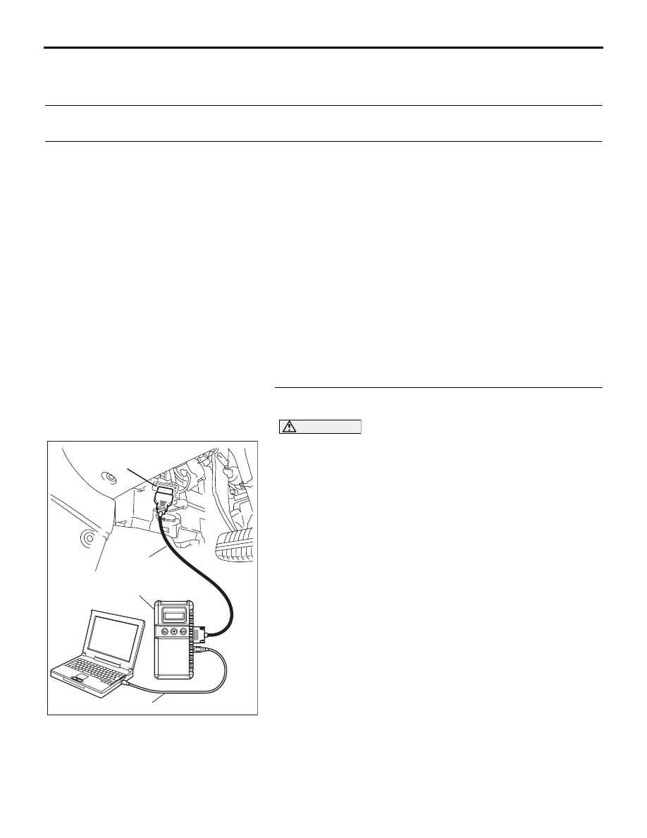
STEP 1. Using diagnostic tool MB991958, diagnose the 
CAN bus line.

CAUTION

To prevent damage to diagnostic tool MB991958, always 
turn the ignition switch to the "LOCK" (OFF) position 
before connecting or disconnecting diagnostic tool 
MB991958.
Use diagnostic tool MB991958 to diagnose the CAN bus lines.
(1) Connect diagnostic tool MB991958 to the data link 

connector.

(2) Turn the ignition switch to the "ON" position.
(3) Diagnose the CAN bus line.

Q: Is the check result satisfactory?

YES : Check and repair the power supply circuit system 

(Refer to 

P.52B-217

).   

NO :  Repair the CAN bus lines (Refer to GROUP 54C, 

Diagnosis-Can Bus Diagnostic Chart ). 

00DB076A

MB991910

DATA LINK

CONNECTOR

MB991824

MB991827

SRS AIR BAG DIAGNOSIS

SUPPLEMENTAL RESTRAINT SYSTEM (SRS)

52B-217

INSPECTION PROCEDURE 2: Power Supply Circuit System

.

CIRCUIT OPERATION

• The SRS-ECU is energized by the ignition switch 

(IG1) through multi-purpose fuse 18 and the 
SRS-ECU terminal 23 and multi-purpose fuse 19 
and the SRS-ECU terminal 24.

• If the power supply to the SRS-ECU has failed, 

diagnostic tool (MUT-III Sub Assembly) will not 
be able to communicate with it.

.

TROUBLESHOOTING HINTS (THE MOST 
LIKELY CAUSES FOR THIS CASE:) 

• Damaged wiring harness or connector

• Defective battery

• Charging system failed

• Malfunction of the SRS-ECU

.

DIAGNOSIS

Required Special Tools:

• MB991958: diagnostic tool (MUT-III Sub Assembly)

• MB991824: Vehicle Communication Interface (V.C.I.)

• MB991827: MUT-III USB Cable

• MB991910: MUT-III Main Harness A (Vehicles with CAN 

communication system)

.

24DB062A

CONNECTOR: C-121

C-121 (Y)

SRS-ECU

42

31

38

27

21

41

28

39

22

30

25

47

36

33

44

34

45

37

48

26

29

23

40

32

43

35

46

24

B

A

C-121

INSTRUMENT

HARNESS

CONNECTOR

(REAR VIEW)

SRS AIR BAG DIAGNOSIS

SUPPLEMENTAL RESTRAINT SYSTEM (SRS)

52B-218

STEP 1. Measure the resistance at SRS-ECU connector 
C-121.
(1) Disconnect the connector C-121.

CAUTION

Do not insert a test probe into the terminal from its front 
side directly, as the connector contact pressure may be 
weakened.
(2) Check for continuity between C-121 harness side connector 

terminals 46 and body ground.
It should be 2 ohms or less.

Q: Is the measured resistance 2 ohms or less?

YES : Then go to Step 2.
NO :  Repair the wiring harness between SRS-ECU 

connector C-121 terminals 46 and the body ground. 
Then go to Step 5.

STEP 2. Check the harness wires for short circuit to 
ground between SRS-ECU connector C-121 (terminal 
No.23 and 24) and ignition switch connector C-308 
(terminal No.2).

24DB062A

CONNECTOR: C-121

C-121 (Y)

SRS-ECU

42

31

38

27

21

41

28

39

22

30

25

47

36

33

44

34

45

37

48

26

29

23

40

32

43

35

46

24

B

A

C-121

INSTRUMENT

HARNESS

CONNECTOR

(REAR VIEW)

24DB059A

42

31

38

27

21

41

28

39

22

30

25

47

36

33

44

34

45

37

48

26

29

23

40

32

43

35

46

24

B

A

C-121 HARNESS SIDE 
CONNECTOR (REAR VIEW)

35DB042A

CONNECTOR: C-308

C-308

2

5

4

1

6

3

24DB062A

CONNECTOR: C-121

C-121 (Y)

SRS-ECU

42

31

38

27

21

41

28

39

22

30

25

47

36

33

44

34

45

37

48

26

29

23

40

32

43

35

46

24

B

A

C-121

INSTRUMENT

HARNESS

CONNECTOR

(REAR VIEW)

SRS AIR BAG DIAGNOSIS

SUPPLEMENTAL RESTRAINT SYSTEM (SRS)

52B-219

NOTE: After inspecting intermediate connectors , C-211 and 
C-215 inspect the wiring harness. If intermediate connectors , 
C-211 and C-215 are damaged, repair or replace wiring har-
ness. Refer to GROUP 00E, Harness Connector Inspection . 
Then go to Step 5.

Q: Are the harness wires between SRS-ECU connector 

C-121 (terminal No.23 and 24) and ignition switch 
connector C-308 (terminal No.2) in good condition?
YES : 
Go to Step 3.
NO :  Replace the harness wires between SRS-ECU 

connector C-121 and ignition switch connector C-308. 
Then go to Step 5.

STEP 3. Check the battery.
Check the battery (Refer to GROUP 54A, Battery test ).

Q: Is the battery in good condition?

YES : Go to Step 4.
NO :  Charge or replace the battery. Then go to Step 5.

STEP 4. Check the charging system.
Check the charging system (Refer to GROUP 16, Charging 
system diagnosis ).

Q: Is the charging system in good condition?

YES : Go to Step 5.
NO :  Repair or replace the charging system 

component(s).Then go to Step 5.

STEP 5. Retest the system.

Q: Can the SRS-ECU communicate with the diagnostic tool 

(MUT-III Sub Assembly)?
YES : 
It can be assumed that this malfunction is intermittent. 

Refer to GROUP 00, How to Use 
Troubleshooting/Inspection Service Points 

− How to 

Cope with Intermittent Malfunctions .

NO :  Replace the SRS-ECU (Refer to 

P.52B-234

). Then go 

to Step 6.

STEP 6. Retest the system.

Q: Can the SRS-ECU communicate with the diagnostic tool 

(MUT-III Sub Assembly)?
YES : 
The procedure is complete.
NO :  Go to Step 1.

52DB021A

CONNECTORS: C-211, C-215

HARNESS SIDE

C-211

HARNESS SIDE

C-215


Content   ..  821  822  823  824   ..