Mitsubishi 380. Manual - part 510


  Index      Mitsubishi     Mitsubishi 380 - service repair manual 2005 year


Search            


Content   ..  508  509  510  511   ..


Mitsubishi 380. Manual - part 510


MULTIPOINT FUEL INJECTION (MPI) DIAGNOSIS

MULTIPOINT FUEL INJECTION (MPI)

13A-132

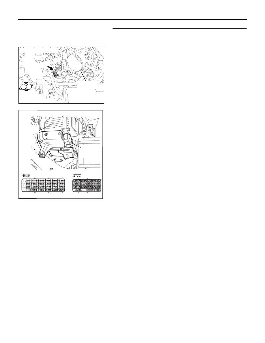
STEP 9. Check for harness damage between engine 
coolant temperature sensor connector B-104 (terminal No. 
1) and ENGINE-ECU connector B-20 (terminal No. 56).
Q: Is the harness wire in good condition?

YES : Then go to Step 10.
NO :  Repair it. Then go to Step 11.

1

2

AK303037

HARNESS

CONNECTOR:

COMPONENT SIDE

CONNECTOR: B-104

AB

B-104 (B)

THROTTLE

BODY

16DB400A

COVER

ENGINE

CONTROL

UNIT

AIR

CLEANER

MULTIPOINT FUEL INJECTION (MPI) DIAGNOSIS

MULTIPOINT FUEL INJECTION (MPI)

13A-133

STEP 10. Using diagnostic tool , check data list item 6: 
Engine Coolant Temperature Sensor.

CAUTION

To prevent damage to diagnostic tool , always turn the 
ignition switch to the "LOCK" (OFF) position before con-
necting or disconnecting diagnostic tool .
(1) Connect diagnostic tool  to the data link connector.
(2) Turn the ignition switch to the "ON" position.
(3) Set diagnostic tool  to the data reading mode for item 6, 

Engine Coolant Temperature Sensor.

• The engine coolant temperature and temperature 

shown with the diagnostic tool should approximately 
match.

(4) Turn the ignition switch to the "LOCK" (OFF) position.

Q: Is the sensor operating properly?

YES : The inspection is complete.
NO :  Then go to Step 11.

STEP 11. Test the EOBD drive cycle.
(1) Carry out a test drive with the drive cycle pattern. Refer to 

Diagnostic Function 

− EOBD Drive Cycle − 

P.13A-11

.

(2) Check the diagnostic trouble code (DTC).

Q: Is DTC P0116 set?

YES : Retry the troubleshooting.
NO :  The inspection is complete.

00DB076A

MB991910

DATA LINK

CONNECTOR

MB991824

MB991827

MULTIPOINT FUEL INJECTION (MPI) DIAGNOSIS

MULTIPOINT FUEL INJECTION (MPI)

13A-134

DTC P0117: Engine Coolant Temperature Circuit Low Input.

CAUTION

If DTC P0117 has been set, TCL and air condi-
tioner related DTC U1120 is also set. After P0117 
has been diagnosed, don't forget to erase DTC 
U1120.

.

CIRCUIT OPERATION

• 5-volt voltage is applied to the engine coolant 

temperature sensor output terminal (terminal No. 
1) from the ENGINE-ECU (terminal No. 56) via 
the resistor in the ENGINE-ECU. The ground ter-
minal (terminal No. 2) is grounded with 
ENGINE-ECU (terminal No. 12).

• The engine coolant temperature sensor is a neg-

ative temperature coefficient type of resistor. It 
has the characteristic that when the engine cool-
ant temperature rises the resistance decreases.

• The engine coolant temperature sensor output 

voltage increases when the resistance increases 
and decreases when the resistance decreases.

.

TECHNICAL DESCRIPTION

• The engine coolant temperature sensor converts 

the engine coolant temperature to a voltage and 
outputs it.

• The ENGINE-ECU checks whether this voltage is 

within a specified range.

.

DTC SET CONDITIONS

Check Conditions

• Mass air flow.

Judgement Criteria

• Engine coolant temperature is below -39 

degreeC for 0.5 second.

• MIL is activated after 2 Drive cycles.

• No limp home mode.

.

EOBD DRIVE CYCLE PATTERN

Refer to Diagnostic Function 

− EOBD Drive Cycle − 

P.13A-11

.

.

TROUBLESHOOTING HINTS (The most 
likely causes for this code to be set are:)

• Engine coolant temperature sensor failed.

• Shorted engine coolant temperature sensor cir-

cuit, or connector damage.

• Refer to component locations GROUP-

70

• Refer to configuration diagrams GROUP-

80

• Refer to circuit diagrams GROUP-

90

DIAGNOSIS

Required Special Tools:

• : Diagnostic Tool (MUT-III Sub Assembly)

• MB991824: V.C.I.

• MB991827: USB Cable

• MB991910: Main Harness A

AK303036

CONNECTOR: B-104

AB

B-104 (B)

ENGINE

COOLANT

TEMPERATURE

SENSOR

THROTTLE

BODY

16DB400A

COVER

ENGINE

CONTROL

UNIT

AIR

CLEANER

MULTIPOINT FUEL INJECTION (MPI) DIAGNOSIS

MULTIPOINT FUEL INJECTION (MPI)

13A-135

STEP 1. Using diagnostic tool , check data list item 6: 
Engine Coolant Temperature Sensor.

CAUTION

To prevent damage to diagnostic tool , always turn the 
ignition switch to the "LOCK" (OFF) position before con-
necting or disconnecting diagnostic tool .
(1) Connect diagnostic tool  to the data link connector.
(2) Turn the ignition switch to the "ON" position.
(3) Set diagnostic tool  to the data reading mode for item 6, 

Engine Coolant Temperature Sensor.

• The actual engine coolant temperature and the temper-

ature shown with the diagnostic tool should approxi-
mately match.

(4) Turn the ignition switch to the "LOCK" (OFF) position.

Q: Is the sensor operating properly?

YES : It can be assumed that this malfunction is intermittent. 

Refer to GROUP 00, How to Use 
Troubleshooting/Inspection Service Points 

− How to 

Cope with Intermittent Malfunctions 

P.00-14

.

NO :  Go to Step 2.

STEP 2. Check harness connector B-104 at the engine 
coolant temperature sensor for damage.
Q: Is the harness connector in good condition?

YES : Go to Step 3.
NO :  Repair or replace it. Refer to GROUP 00E, Harness 

Connector Inspection 

P.00E-2

. Then go to Step 7.

00DB076A

MB991910

DATA LINK

CONNECTOR

MB991824

MB991827

1

2

AK303037

HARNESS

CONNECTOR:

COMPONENT SIDE

CONNECTOR: B-104

AB

B-104 (B)

THROTTLE

BODY


Content   ..  508  509  510  511   ..