Mitsubishi 380. Manual - part 508


  Index      Mitsubishi     Mitsubishi 380 - service repair manual 2005 year


Search            


Content   ..  506  507  508  509   ..


Mitsubishi 380. Manual - part 508


MULTIPOINT FUEL INJECTION (MPI) DIAGNOSIS

MULTIPOINT FUEL INJECTION (MPI)

13A-124

STEP 7. Check harness connector B-20 at ENGINE-ECU for 
damage.
Q: Is the harness connector in good condition?

YES : It can be assumed that this malfunction is intermittent. 

Refer to GROUP 00, How to Use 
Troubleshooting/Inspection Service Points 

− How to 

Cope with Intermittent Malfunctions 

P.00-14

.

NO :  Repair or replace it. Refer to GROUP 00E, Harness 

Connector Inspection 

P.00E-2

. Then go to Step 11.

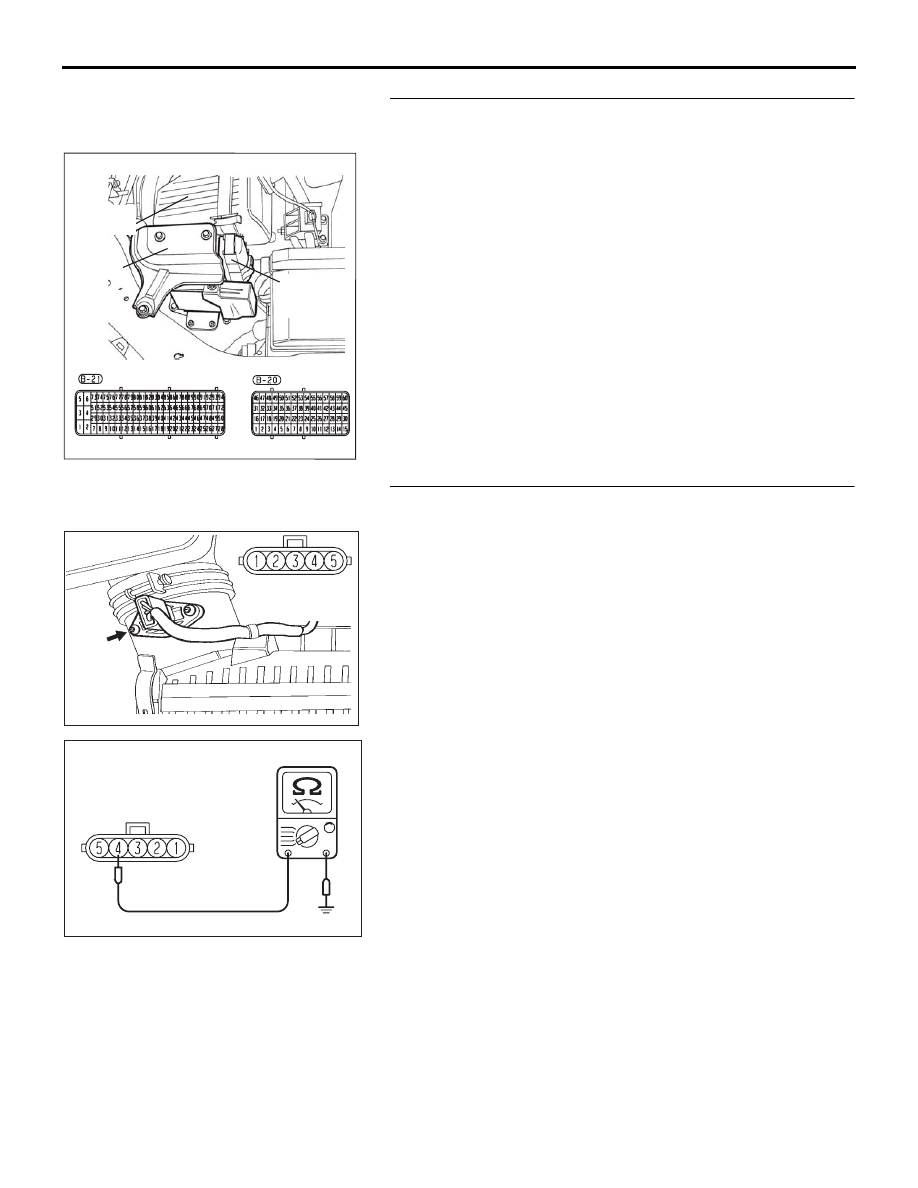
STEP 8. Check the continuity at intake air temperature 
sensor harness side connector B-10.
(1) Disconnect the connector B-10 and measure at the harness 

side.

(2) Check for the continuity between terminal No. 3 and 

ground.

• Should be less than 2 ohms.

Q: Does continuity exist?

YES : Then go to Step 11.
NO :  Go to Step 9.

16DB400A

COVER

ENGINE

CONTROL

UNIT

AIR

CLEANER

CONNECTOR: B-10

B-10 (GR)

03DB218A

HARNESS

CONNECTOR:

COMPONENT SIDE

03DB219A

B-10 HARNESS 

CONNECTOR: 

COMPONENT SIDE

MULTIPOINT FUEL INJECTION (MPI) DIAGNOSIS

MULTIPOINT FUEL INJECTION (MPI)

13A-125

STEP 9. Check harness connector B-20 at ENGINE-ECU for 
damage.
Q: Is the harness connector in good condition?

YES : Go to Step 10.
NO :  Repair or replace it. Refer to GROUP 00E, Harness 

Connector Inspection 

P.00E-2

. Then go to Step 11.

STEP 10. Check for open circuit between intake air 
temperature sensor connector B-10 (terminal No. 3) and 
ENGINE-ECU connector B-20 (terminal No. 26).
Q: Is the harness wire in good condition?

YES : Then go to Step 11.
NO :  Repair it. Then go to Step 11.

16DB400A

COVER

ENGINE

CONTROL

UNIT

AIR

CLEANER

CONNECTOR: B-10

B-10 (GR)

03DB218A

HARNESS

CONNECTOR:

COMPONENT SIDE

16DB400A

COVER

ENGINE

CONTROL

UNIT

AIR

CLEANER

MULTIPOINT FUEL INJECTION (MPI) DIAGNOSIS

MULTIPOINT FUEL INJECTION (MPI)

13A-126

STEP 11. Test the EOBD drive cycle.
(1) Carry out a test drive with the drive cycle pattern. Refer to 

Diagnostic Function 

− EOBD Drive Cycle − 

P.13A-11

.

(2) Check the diagnostic trouble code (DTC).

Q: Is DTC P0113 set?

YES : Retry the troubleshooting.
NO :  The inspection is complete.

MULTIPOINT FUEL INJECTION (MPI) DIAGNOSIS

MULTIPOINT FUEL INJECTION (MPI)

13A-127

DTC P0116: Engine Coolant Temperature Circuit Range/Performance Problem.

CAUTION

If DTC P0116 has been set, TCL related DTC 
U1120 is also set. After P0116 has been diag-
nosed, don't forget to erase DTC U1120.

.

CIRCUIT OPERATION

• 5-volt voltage is applied to the engine coolant 

temperature sensor output terminal (terminal No. 
1) from the ENGINE-ECU (terminal No. 56) via 
the resistor in the ENGINE-ECU. The ground ter-
minal (terminal No. 2) is grounded with 
ENGINE-ECU (terminal No. 12).

• The engine coolant temperature sensor is a neg-

ative temperature coefficient type of resistor. It 
has the characteristic that when the engine cool-
ant temperature rises the resistance decreases.

• The engine coolant temperature sensor output 

voltage increases when the resistor increases 
and decreases when the resistance decreases.

.

TECHNICAL DESCRIPTION

• The engine coolant temperature sensor converts 

the engine coolant temperature to a voltage and 
outputs it.

• The ENGINE-ECU checks whether this voltage is 

within a specified range.

.

DTC SET CONDITIONS

Check Conditions

• Air mass flow.

Judgement Criteria

• Difference between real engine temperature and 

model temperature.

• MIL is activated after 2 Drive cycles.

• No limp home mode.

.

EOBD DRIVE CYCLE PATTERN

Refer to Diagnostic Function

−EOBD Drive Cycle− 

P.13A-11

.

.

TROUBLESHOOTING HINTS (The most 
likely causes for this code to be set are:)

• Engine coolant temperature sensor failed.

• Harness damage or connector damage.

• Refer to component locations GROUP-

70

• Refer to configuration diagrams GROUP-

80

• Refer to circuit diagrams GROUP-

90

DIAGNOSIS

Required Special Tools:

• : Diagnostic Tool (MUT-III Sub Assembly)

• MB991824: V.C.I.

• MB991827: USB Cable

• MB991910: Main Harness A

AK303036

CONNECTOR: B-104

AB

B-104 (B)

ENGINE

COOLANT

TEMPERATURE

SENSOR

THROTTLE

BODY

AK303013

CONNECTORS: B-21, B-22

PCM

AB

AIR CLEANER

B-22 (B)

B-21 (B)


Content   ..  506  507  508  509   ..