Mitsubishi 380. Manual - part 511
 

  Index      Mitsubishi     Mitsubishi 380 - service repair manual 2005 year


Search            


Content   ..  509  510  511  512   ..


Mitsubishi 380. Manual - part 511


MULTIPOINT FUEL INJECTION (MPI) DIAGNOSIS

MULTIPOINT FUEL INJECTION (MPI)

13A-136

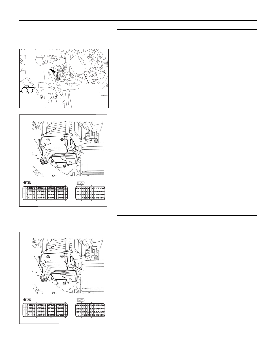
STEP 3. Check for short circuit to ground between engine 
coolant temperature sensor connector B-104 (terminal No. 
1) and ENGINE-ECU connector B-20 (terminal No. 56).
Q: Is the harness wire in good condition?

YES : Go to Step 4.
NO :  Repair it. Then go to Step 7.

STEP 4. Check harness connector B-20 at ENGINE-ECU for 
damage.
Q: Is the harness connector in good condition?

YES : Go to Step 5.
NO :  Repair or replace it. Refer to GROUP 00E, Harness 

Connector Inspection 

P.00E-2

. Then go to Step 7.

1

2

AK303037

HARNESS

CONNECTOR:

COMPONENT SIDE

CONNECTOR: B-104

AB

B-104 (B)

THROTTLE

BODY

16DB400A

COVER

ENGINE

CONTROL

UNIT

AIR

CLEANER

16DB400A

COVER

ENGINE

CONTROL

UNIT

AIR

CLEANER

MULTIPOINT FUEL INJECTION (MPI) DIAGNOSIS

MULTIPOINT FUEL INJECTION (MPI)

13A-137

STEP 5. Check the engine coolant temperature sensor(On 
Car).
(1) Ensure engine coolant temperature is between 20

° C and 

below 100

° C.

(2) Disconnect the engine coolant temperature sensor 

connector B-104.

(3) Check the resistance between terminal No. 1 & No. 2 of the 

sensor.

Q: Is the measured resistance between 186

 and 2.4 k?

YES : Go to Step 6.
NO :  Replace the sensor and go to Step 7.

STEP 6. Check the engine coolant temperature sensor(Off 
Car).
(1) Disconnect the engine coolant temperature sensor 

connector B-104.

(2) Remove the engine coolant temperature sensor.

WARNING

Ensure cooling system pressure is released at radia-
tor cap slowly, prior to removing sensor to avoid get-
ting burned by hot coolant.

(3) With the temperature sensing portion of engine coolant 

temperature sensor immersed in hot water, measure 
resistance.Refer to Service Specifications 

13A-677

(4) Apply 3M

™ AAD part number 8731 or equivalent on the 

screw section of the engine coolant temperature sensor.

(5) Install the engine coolant temperature sensor, and tighten 

to the specified torque.

Tightening torque: 21 

± 3 N

Q: Is the measured resistance at the standard value?

YES : Then go to Step 7.
NO :  Replace the engine coolant sensor. Then go to Step 

7.

1

2

AK303037

HARNESS

CONNECTOR:

COMPONENT SIDE

CONNECTOR: B-104

AB

B-104 (B)

THROTTLE

BODY

1

2

AK303037

HARNESS

CONNECTOR:

COMPONENT SIDE

CONNECTOR: B-104

AB

B-104 (B)

THROTTLE

BODY

AKX01622

AKX01623 AB

MULTIPOINT FUEL INJECTION (MPI) DIAGNOSIS

MULTIPOINT FUEL INJECTION (MPI)

13A-138

STEP 7. Test the EOBD drive cycle.
(1) Carry out a test drive with the drive cycle pattern. Refer to 

Diagnostic Function 

− EOBD Drive Cycle − 

P.13A-11

.

(2) Check the diagnostic trouble code (DTC).

Q: Is DTC P0117 set?

YES : Retry the troubleshooting.
NO :  The inspection is complete.

MULTIPOINT FUEL INJECTION (MPI) DIAGNOSIS

MULTIPOINT FUEL INJECTION (MPI)

13A-139

DTC P0118: Engine Coolant Temperature Circuit High Input.

CAUTION

If DTC P0118 has been set, TCL and air condi-
tioner related DTC U1120 is also set. After P0118 
has been diagnosed, don't forget to erase DTC 
U1120.

.

CIRCUIT OPERATION

• 5-volt voltage is applied to the engine coolant 

temperature sensor output terminal (terminal No. 
1) from the ENGINE-ECU (terminal No. 56) via 
the resistor in the ENGINE-ECU. The ground ter-
minal (terminal No. 2) is grounded with 
ENGINE-ECU (terminal No. 12).

• The engine coolant temperature sensor is a neg-

ative temperature coefficient type of resistor. It 
has the characteristic that when the engine cool-
ant temperature rises the resistance decreases.

• The engine coolant temperature sensor output 

voltage increases when the resistance increases 
and decreases when the resistance decreases.

.

TECHNICAL DESCRIPTION

• The engine coolant temperature sensor converts 

the engine coolant temperature to a voltage and 
outputs it.

• The ENGINE-ECU checks whether this voltage is 

within a specified range.

.

DTC SET CONDITIONS

Check Conditions

• Mass air flow.

Judgement Criteria

• Engine coolant temperature is above 138.8 

degreeC for 0.5 second.

.

EOBD DRIVE CYCLE PATTERN

Refer to Diagnostic Function

−EOBD Drive Cycle− 

P.13A-11

.

.

TROUBLESHOOTING HINTS (The most 
likely causes for this code to be set are: )

• Engine coolant temperature sensor failed.

• Open engine coolant temperature sensor circuit, 

or connector damage.

• Short to 12 volt.

• Refer to component locations GROUP-

70

• Refer to configuration diagrams GROUP-

80

• Refer to circuit diagrams GROUP-

90

DIAGNOSIS

Required Special Tools:

• : Diagnostic Tool (MUT-III Sub Assembly)

• MB991824: V.C.I.

• MB991827: USB Cable

• MB991910: Main Harness A

• MB992044:  ECU Check Harness

AK303036

CONNECTOR: B-104

AB

B-104 (B)

ENGINE

COOLANT

TEMPERATURE

SENSOR

THROTTLE

BODY

16DB400A

COVER

ENGINE

CONTROL

UNIT

AIR

CLEANER


Content   ..  509  510  511  512   ..