Mitsubishi 380. Manual - part 279


  Index      Mitsubishi     Mitsubishi 380 - service repair manual 2005 year


Search            


Content   ..  277  278  279  280   ..


Mitsubishi 380. Manual - part 279


DOOR

BODY

42-48

REMOVAL SERVICE POINT

.

<<A>> DOOR LOCK KEY CYLINDER ASSEMBLY 
REMOVAL

1. Create clearance between the door panel and the door 

outside handle to access the pin.

2. Open the pin and remove the door lock key cylinder 

assembly.

INSTALLATION SERVICE POINTS

.

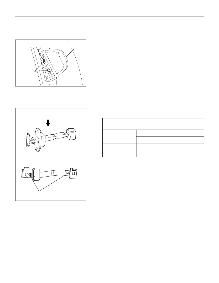
>>A<< DOOR CHECK INSTALLATION

Install the door check so that the identification mark faces 
upwards.

.

>>B<< LOWER SASH INSTALLATION

Securely insert the lower sash into the window rear sash.

18DB162A

PIN

DOOR OUTSIDE 

HANDLE

DOOR LOCK KEY 

CYLINDER ASSEMBLY

ITEM

IDENTIFICATION 
MARK

Front Door

Left door

P4FL

Right door

P4FR

Rear Door

Left door

P4RL

Right door

P4RR

AC204902

A

VIEW A

IDENTIFICATION MARK

AB

DOOR

BODY

42-49

INSPECTION

M1423004700411

FRONT DOOR LATCH CHECK

The illustration shows when the door lock actuator is viewed 
from inside the door.

DOOR LOCK ACTUATOR CHECK <LEFT SIDE>

DOOR LOCK ACTUATOR SWITCH CHECK <LEFT SIDE>

DOOR LOCK ACTUATOR CHECK <RIGHT SIDE>

LEVER 
POSITION

BATTERY CONNECTION

LEVER 
OPERATION

At the 
"LOCK" 
position

• Connect terminal No. 4 

and the negative battery 
terminal.

• Connect terminal No. 6 

and the positive battery 
terminal.

The lever moves 
from the "LOCK" 
position to the 
"UNLOCK" 
position.

At the 
"UNLOCK" 
position

• Connect terminal No. 6 

and the negative battery 
terminal.

• Connect terminal No. 4 

and the positive battery 
terminal.

The lever moves 
from the 
"UNLOCK" 
position to the 
"LOCK" position.

LEVER POSITION TESTER 

CONNECTION

SPECIFIED 
CONDITION

At the "LOCK" 
position

− 2

Open circuit

At the "UNLOCK" 
position

− 2

Less than 2 ohms

LEVER 
POSITION

BATTERY CONNECTION

LEVER 
OPERATION

At the 
"LOCK" 
position

• Connect terminal No. 6 

and the negative battery 
terminal.

• Connect terminal No. 4 

and the positive battery 
terminal.

The lever moves 
from the "LOCK" 
position to the 
"UNLOCK" 
position.

At the 
"UNLOCK" 
position

• Connect terminal No. 4 

and the negative battery 
terminal.

• Connect terminal No. 6 

and the positive battery 
terminal.

The lever moves 
from the 
"UNLOCK" 
position to the 
"LOCK" position.

1 2 3

4 5 6

AC210729

1 2 3

4 5 6

AB

VIEW A

VIEW B

FRONT DOOR

<LEFT SIDE>

<RIGHT SIDE>

A

B

LOCK

UNLOCK

LOCK

LEVER

UNLOCK

LEVER

DOOR

BODY

42-50

DOOR LOCK ACTUATOR SWITCH CHECK <RIGHT SIDE>

REAR DOOR LOCK ACTUATOR CHECK

The illustration shows when the door lock actuator is viewed 
from outside the door.

DOOR LOCK ACTUATOR CHECK <LEFT SIDE>

DOOR LOCK ACTUATOR CHECK <RIGHT SIDE>

LEVER POSITION TESTER 

CONNECTION

SPECIFIED 
CONDITION

At the "LOCK" 
position

− 3

Open circuit

At the "UNLOCK" 
position

− 3

Less than 2 ohms

LEVER 
POSITION

BATTERY CONNECTION

LEVER 
OPERATION

At the 
"LOCK" 
position

• Connect terminal No. 6 

and the negative battery 
terminal.

• Connect terminal No. 4 

and the positive battery 
terminal.

The lever moves 
from the "LOCK" 
position to the 
"UNLOCK" 
position.

At the 
"UNLOCK" 
position

• Connect terminal No. 4 

and the negative battery 
terminal.

• Connect terminal No. 6 

and the positive battery 
terminal.

The lever moves 
from the 
"UNLOCK" 
position to the 
"LOCK" position.

LEVER 
POSITION

BATTERY CONNECTION

LEVER 
OPERATION

At the 
"LOCK" 
position

• Connect terminal No. 4 

and the negative battery 
terminal.

• Connect terminal No. 6 

and the positive battery 
terminal.

The lever moves 
from the "LOCK" 
position to the 
"UNLOCK" 
position.

At the 
"UNLOCK" 
position

• Connect terminal No. 6 

and the negative battery 
terminal.

• Connect terminal No. 4 

and the positive battery 
terminal.

The lever moves 
from the 
"UNLOCK" 
position to the 
"LOCK" position.

AC210730

1 2 3

4 5 6

1 2 3

4 5 6

A

B

AB

VIEW A

VIEW B

REAR DOOR

<LEFT SIDE>

<RIGHT SIDE>

LOCK

UNLOCK

LOCK

UNLOCK

LEVER

LEVER

DOOR

BODY

42-51

FUEL LID D00R ACTUATOR CHECK

DOOR LOCK KEY CYLINDER SWITCH CHECK

CENTRAL DOOR LOCK SWITCH CONTINUITY 
CHECK

Remove the power window switch (Refer to 

P.42-39

).

<DRIVER'S SIDE>

LEVER 
POSITION

BATTERY CONNECTION

LEVER 
OPERATION

At the 
"LOCK" 
position

• Connect terminal No. 1 

and the negative battery 
terminal.

• Connect terminal No. 2 

and the positive battery 
terminal.

The lever moves 
from the "LOCK" 
position to the 
"UNLOCK" 
position.

At the 
"UNLOCK" 
position

• Connect terminal No. 2 

and the negative battery 
terminal.

• Connect terminal No. 1 

and the positive battery 
terminal.

The lever moves 
from the 
"UNLOCK" 
position to the 
"LOCK" position.

SWITCH 
POSITION

TESTER 
CONNECTION

SPECIFIED 
CONDITION

LOCK

− 3

Less than 2 ohms

NEUTRAL (OFF)

− 2, 2 − 3

Open circuit

UNLOCK

− 2

Less than 2 ohms

AC210743

1

3

2

SWITCH 
POSITION

TESTER 
CONNECTION

SPECIFIED 
CONDITION

LOCK

− 5

Less than 2 ohms

OFF

− 5, 2 − 13

Open circuit

UNLOCK

− 13

Less than 2 ohms

18DB165A

DOOR LOCK

SWITCH

8

3

4 5

1

2

6 7


Content   ..  277  278  279  280   ..