Mitsubishi 380. Manual - part 277
DOOR
BODY
42-40
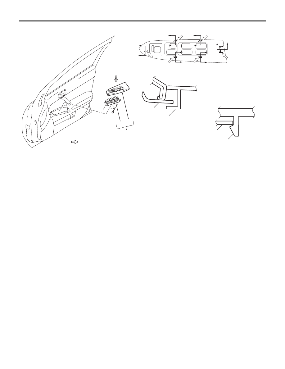
Required Special Tool:
• MB990784: Ornament Remover
18DB160A
AC306724
NOTE
: CLAW POSITIONS
A
3
VIEW A
4
5
SECTION B – B
SECTION C – C
B
B
C
C
C
C
C
C
C
C
C
CLAW
CLAW
TRIM
TRIM
<FRONT DOOR POWER WINDOW SWITCH>
C
POWER WINDOW SWITCH
REMOVAL STEPS
<<C>>
3. POWER WINDOW SWITCH PANEL
ASSEMBLY
4. POWER WINDOW SWITCH PANEL
5. POWER WINDOW MAIN SWITCH
(LH), POWER WINDOW SUB
SWITCH (RH)