Mitsubishi Grandis. Manual - part 986


  Index      Mitsubishi     Mitsubishi Grandis - service repair manual


Search            


Content   ..  984  985  986  987   ..


Mitsubishi Grandis. Manual - part 986


POWER STEERING OIL PUMP ASSEMBLY

POWER STEERING

37-34

ASSEMBLY SERVICE POINTS
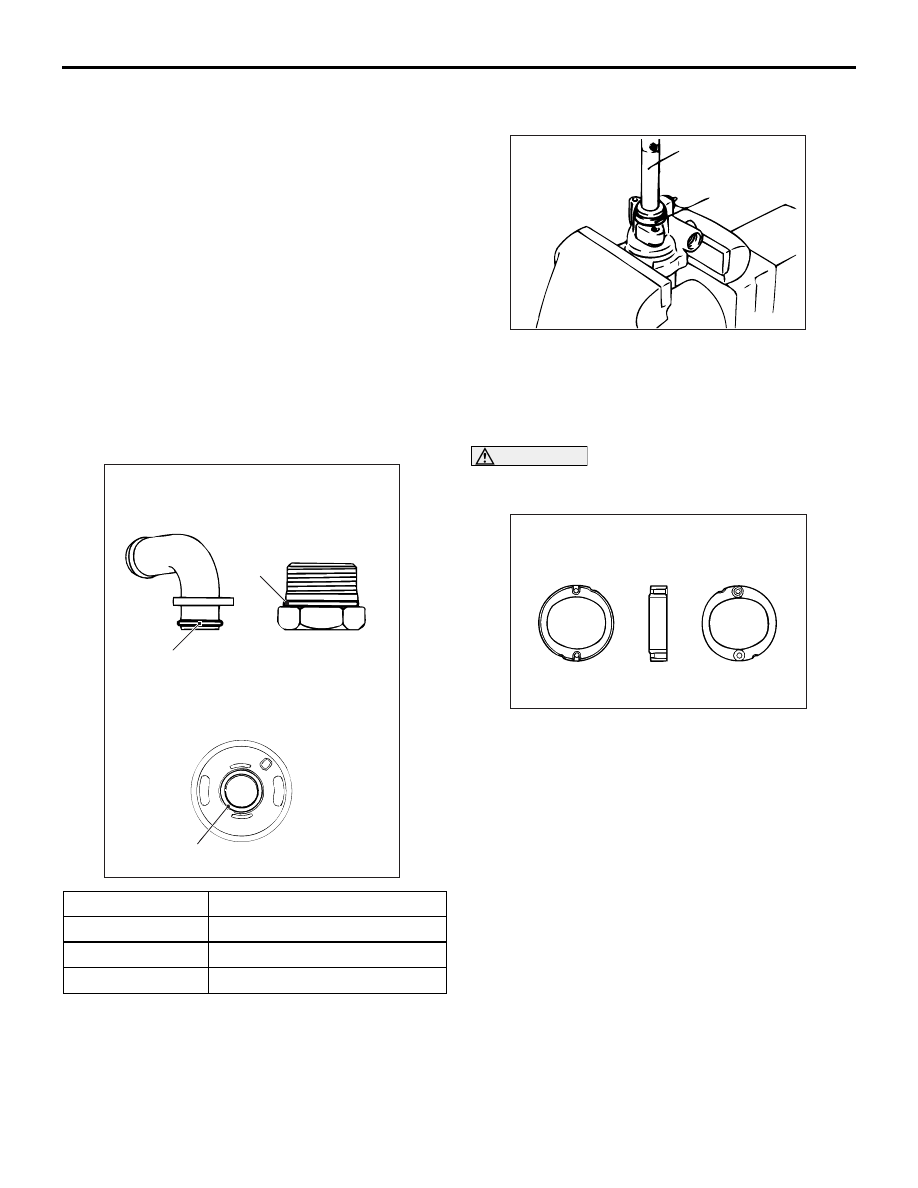
>>A<< O-RING INSTALLATION

>>B<< OIL SEAL INSTALLATION

Use following special tool to install the oil seal.

• MB990938: Bar (Snap-in type)

• MB991203: Oil Seal and Bearing Installer

>>C<< CAM RING INSTALLATION

CAUTION

Be sure to install the cam ring in the correct 
direction as shown.

Install the cam ring as shown in the illustration.

INSPECTION

M1372005500288

• Check the flow control valve of the pump body for 

clogging.

• Check the pulley and shaft for wear or damage.

• Check the rotor and vane groove for "stepped" 

wear.

• Check the contact surface of cam ring and vanes 

for "stepped" wear.

• Check the vanes for damage.

Disassembly steps

1.

Pump cover

2.

O-ring

3.

Snap ring

4.

Pulley and shaft

5.

Vanes

>>C<<

6.

Cam ring

7.

Rotor

8.

Pin

9.

Side plate

>>A<<

10.

O-ring

>>B<<

11.

Oil seal

12.

Plug assembly

>>A<<

13.

O-ring

14.

Flow control spring

15.

Suction connector

>>A<<

16.

O-ring

No.

ID 

× Width mm

1

15.8 

× 2.4

2

21.0 

× 2.4

3

14.8 

× 1.9

AC303495AC

1

3

2

Suction connector

Plug assembly

Side plate

AC000752

MB990938

AB

MB991203

AC100171AB

Side plate side

Pump cover side

POWER STEERING HOSES

POWER STEERING

37-35

POWER STEERING HOSES

REMOVAL AND INSTALLATION

M1372005700602

Pre-removal and Post-installation Operation
• Power Steering Fluid Draining and Refilling (Refer to 

P.37-11

.) and Bleeding (Refer to 

P.37-11

.)

AC312228

28 ± 2 N·m

13 ± 2 N·m

13 ± 2 N·m

57 ± 7 N·m

N

N

AB

13 ± 2 N·m

N

13 ± 2 N·m

57 ± 7 N·m

15 ± 3 N·m

4

10

11

12

8

1

2

3

5

6

7

13

5

6

9

<LH drive vehicles>

Removal steps

1.

Oil reservoir

>>F<<

2.

Suction hose

>>E<<

3.

Return hose

•.

Stabilizer link

4.

Power steering oil pressure sensor

5.

Eye bolt

6.

Gasket

Brake fluid reservoir assembly 
mounting nut

>>D<<

7.

Pressure hose

>>C<<

8.

Return hose

>>B<<

9.

Return tube

>>A<<

10.

Return hose

11.

Return tube

12.

O-ring

Front bumper assembly (Refer to 
GROUP 51, Front bumper assembly 

P.51-3

.)

13.

Cooler tube

Removal steps (Continued)

POWER STEERING HOSES

POWER STEERING

37-36

INSTALLATION SERVICE POINTS
>>A<< RETURN HOSE INSTALLATION

AC303002

28 ± 2 N·m

13 ± 2 N·m

13 ± 2 N·m

57 ± 7 N·m

N

N

AC

13 ± 2 N·m

13 ± 2 N·m

N

13 ± 2 N·m

57 ± 7 N·m

15 ± 3 N·m

4

8

10

11

9

1

2

3

5

6

7

12

5

6

<RH drive vehicles>

Removal steps

1.

Oil reservoir

>>F<<

2.

Suction hose

>>E<<

3.

Return hose

•.

Stabilizer link

4.

Power steering oil pressure sensor

5.

Eye bolt

6.

Gasket

Brake fluid reservoir assembly 
mounting nut

>>D<<

7.

Pressure hose

>>D<<

8.

Pressure hose bracket

>>A<<

9.

Return hose

10.

Return tube

11.

O-ring

Front bumper assembly (Refer to 
GROUP 51, Front bumper assembly 

P.51-3

.)

12.

Cooler tube

AC311970AB

Return hose

<LH drive vehicles>

Marking

AC302814AC

Marking

Return hose

<RH drive vehicles>

POWER STEERING HOSES

POWER STEERING

37-37

1. Align the marking (white) as shown and connect 

the return hose.

2. Align the marking (yellow) as shown and connect 

the return hose.

>>B<< RETURN TUBE INSTALLATION 
<LH drive vehicles>

Align the return tube marking (green) as shown and 
connect the return tube.

>>C<< RETURN HOSE INSTALLATION 
<LH drive vehicles>

Align the return hose marking (green) as shown and 
connect the return hose.

>>D<< PRESSURE HOSE INSTALLATION

1. Align the pressure hose plate as shown and 

connect pressure hose.

2. When connecting the pressure hose to the 

pressure hose bracket, be careful not to deform 
the top and bottom of the clip and the rubber.

>>E<< RETURN HOSE INSTALLATION

Align the return hose marking (yellow) within the area 
shown and connect the return hose.

AC311971AB

Return hose

Marking

Return tube

<LH drive vehicles>

AC311969AC

Return hose

Return tube

<LH drive vehicles>

Marking

AC311969AB

Return hose

Return tube

<LH drive vehicles>

Marking

AC313111AB

Plate

Pressure hose

<LH drive vehicles>

AC302813 AC

Plate

Pressure hose

<RH drive vehicles>

AC304093AC

Clip
(top)

Clip
(bottom)

Don't deform

<RH drive vehicles>

Don't deform

AC302815AC

Return hose

Suction hose

30˚

30˚

Oil reservoir


Content   ..  984  985  986  987   ..