Mitsubishi Grandis. Manual - part 974
DIFFERENTIAL
AUTOMATIC TRANSMISSION OVERHAUL
23B-52
DIFFERENTIAL
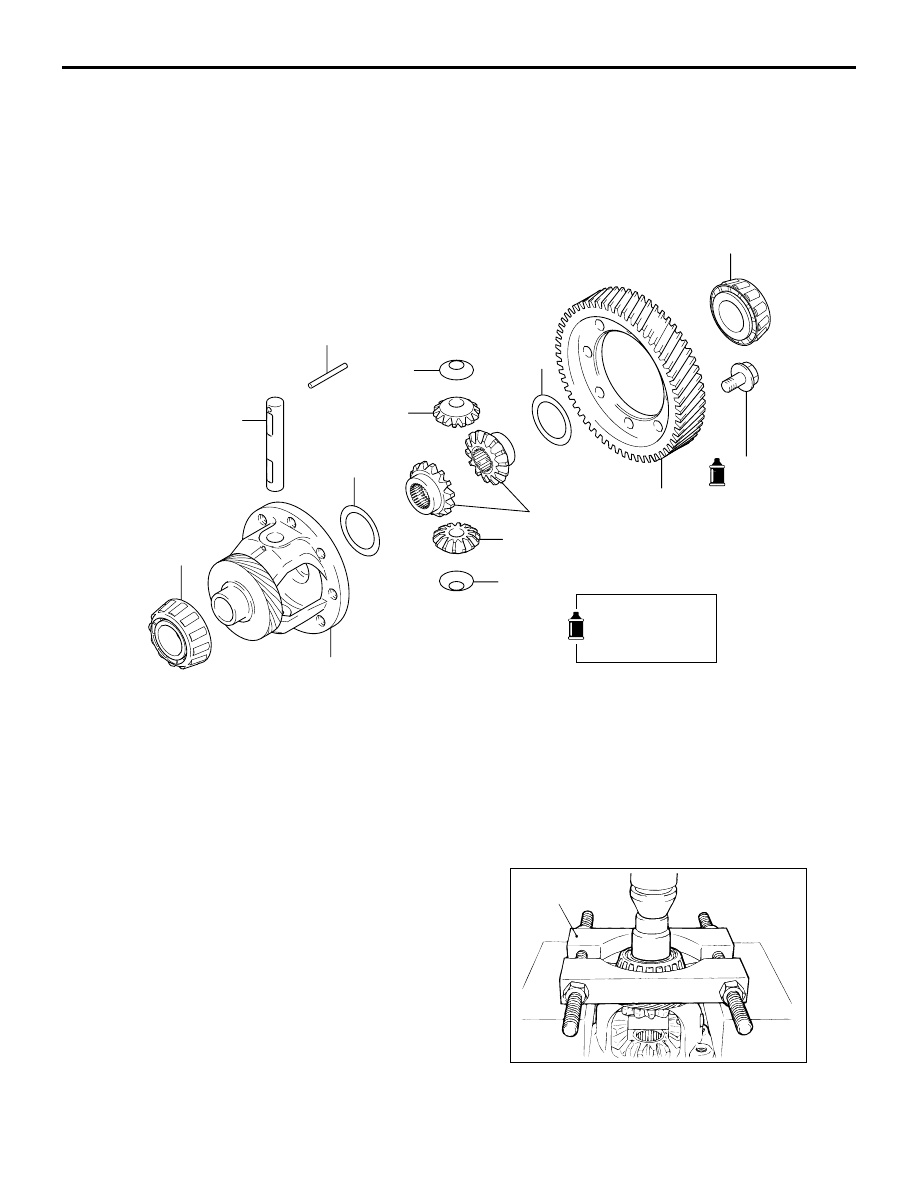
DISASSEMBLY AND REASSEMBLY
M1233003100316
DISASSEMBLY SERVICE POINTS
<<A>> TAPER ROLLER BEARING
REMOVAL
Use the special tool Bearing remover (MD998801) to
remove the taper roller bearings.
AK101411
135 ± 5 N·m
1
2
8
6
5
3
4
7
5
6
8
9
2
AC
Apply automatic
transmission fluid
to all moving parts
before installation.
Disassembly steps
>>D<<
1.
Differential drive gear
<<A>>
>>C<<
2.
Taper roller bearing
>>B<<
3.
Lock pin
>>A<<
4.
Pinion shaft
>>A<<
5.
Pinion
>>A<<
6.
Washer
>>A<<
7.
Side gear
>>A<<
8.
Spacer
9.
Differential case
AK100576
MD998801
AC