Mitsubishi Grandis. Manual - part 972


  Index      Mitsubishi     Mitsubishi Grandis - service repair manual


Search            


Content   ..  970  971  972  973   ..


Mitsubishi Grandis. Manual - part 972


REVERSE AND OVERDRIVE CLUTCH

AUTOMATIC TRANSMISSION OVERHAUL

23B-44

DISASSEMBLY SERVICE POINTS
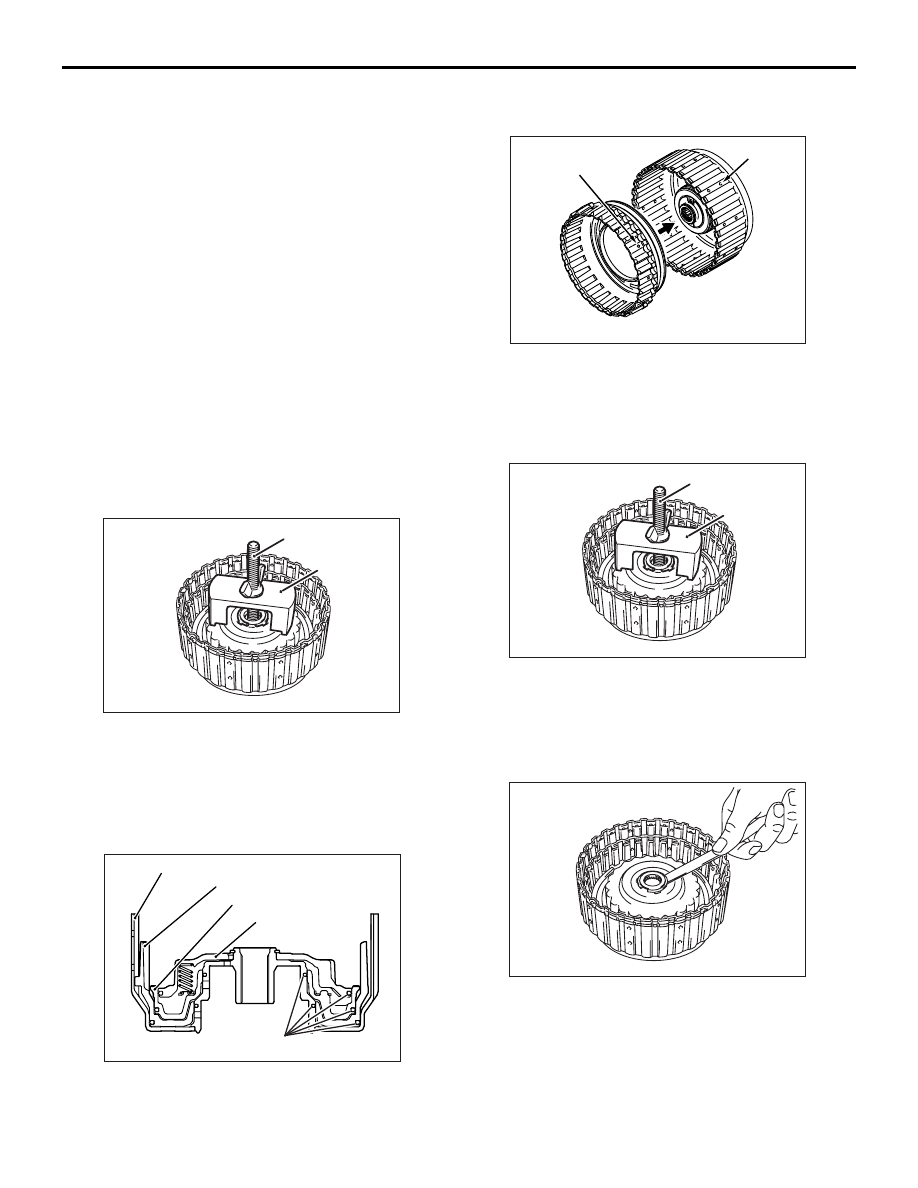
<<A>> SNAP RING REMOVAL

Use the special tools to remove the snap ring.

• Spring compressor retainer (MD998924)

• Spring compressor (MD999590)

REASSEMBLY SERVICE POINTS
>>A<< D-RING INSTALLATION

Apply ATF, blue petrolatum jelly or white Vaseline to 
the D-rings and handle them carefully to avoid 
damage during installation.

>>B<< REVERSE CLUTCH PISTON 
INSTALLATION

Assemble the reverse clutch piston with the reverse 
clutch retainer with their holes (A and B in the 
drawing) aligned.

>>C<< SNAP RING INSTALLATION

1. Use the special tools to install the snap ring.

• Spring compressor retainer (MD998924)

• Spring compressor (MD999590)

2. Press down the return spring retainer tightly on its 

entire circumference (with a force of 49N).

3. Check the clearance between the snap ring and 

the return spring retainer. If the clearance is not 
within the standard value range, make adjustment 
by selecting a snap ring of an appropriate 
thickness.

Standard value: 0 

 0.09 mm

Disassembly steps

>>G<<

1.

Snap ring

>>F<<

2.

Clutch reaction plate

>>F<<

3.

Clutch disc

>>F<<

4.

Clutch plate

>>E<<

5.

Snap ring

>>D<<

6.

Clutch reaction plate

>>D<<

7.

Clutch disc

>>D<<

8.

Clutch plate

<<A>>

>>C<<

9.

Snap ring

10. Spring retainer

>>A<<

11. D-ring
12. Clutch return spring
13. Overdrive clutch piston

>>A<<

14. D-ring

>>B<<

15. Reverse clutch piston

>>A<<

16. D-ring

>>A<<

17. D-ring

>>A<<

18. D-ring
19. Reverse clutch retainer

AK300525AC

MD999590

MD998924

AK301294

D-ring

Reverse clutch retainer

Reverse clutch piston

Overdrive clutch piston

Spring retainer

AB

AK301276AB

A

B

AK300525AC

MD999590

MD998924

AK300526

REVERSE AND OVERDRIVE CLUTCH

AUTOMATIC TRANSMISSION OVERHAUL

23B-45

>>D<< CLUTCH PLATE/CLUTCH 
DISC/CLUTCH REACTION PLATE 
INSTALLATION

CAUTION

Soak the clutch discs in ATF before installing 
them.
1. Assemble the clutch plates, clutch discs, and 

clutch reaction plate with their non-toothed 
portions (A in the drawing) aligned with the hole 
(B in the drawing) formed in a crest of the reverse 
clutch piston.

2. Orient the clutch reaction plate as shown in the 

drawing when it is installed.

>>E<< SNAP RING INSTALLATION

1. Install the snap ring.

2. Press down the clutch reaction plate on the 

circumference using the special tools.

• Spring compressor (MB991628)

• Spring compressor retainer (MD998924)

3. Check the clearance between the snap ring and 

clutch reaction plate. If the clearance is not within 
the standard value range, make adjustment by 
selecting a snap ring of an appropriate thickness.

Standard value: 1.6 

 1.8 mm

>>F<< CLUTCH PLATE/CLUTCH 
DISC/CLUTCH REACTION PLATE 
INSTALLATION

CAUTION

Soak the clutch discs in ATF before installing 
them.
1. Assemble the clutch plates, clutch discs, and 

reaction plate with their non-toothed portions (A in 
the drawing) aligned with the hole (B in the 
drawing) formed in a crest of the reverse retainer.

2. Orient the clutch reaction plate as shown in the 

drawing when it is installed.

>>G<< SNAP RING INSTALLATION

1. Install the snap ring.

AK301272AB

A

B

AK202043

Clutch 
plates

Clutch 
reaction 
plate

Clutch discs

Shear droop

AB

AK202313

MD998924

MB991628

AD

AK301272AB

A

B

AK301320 AB

Clutch plates

Shear droop

Clutch reaction plate

Clutch discs

PLANETARY CARRIER ASSEMBLY

AUTOMATIC TRANSMISSION OVERHAUL

23B-46

2. Press down the clutch reaction plate on its entire 

circumference using the special tools.

• Spring compressor (MB991790)

• Spring compressor retainer (MD998924)

3. Check the clearance between the snap ring and 

the clutch reaction plate. If the clearance is not 
within the standard value range, make adjustment 
by selecting a snap ring of an appropriate 
thickness.

Standard value: 1.5 

 1.7 mm 

PLANETARY CARRIER ASSEMBLY

DISASSEMBLY AND REASSEMBLY

M1233002500151

AK301277AB

MD998924

MB991790

Clearance

AK301044AC

1

2

3

4

5

6

7

8

9

10

Apply automatic
transmission fluid
to all moving parts
before installation.

PLANETARY CARRIER ASSEMBLY

AUTOMATIC TRANSMISSION OVERHAUL

23B-47

REASSEMBLY SERVICE POINTS
>>A<< THRUST BEARING #3/#4 
INSTALLATION

CAUTION

Make sure the ends of each thrust bearing are 
oriented correctly.
Install the thrust bearings #3 and #4 in position as 
shown in the drawing.

>>B<< ONE-WAY CLUTCH 
INSTALLATION

Insert the one-way clutch into the overdrive annulus 
gear with the arrow pointing as shown in the drawing.

Disassembly steps

1.

Stopper plate

>>B<<

2.

One-way clutch

3.

Snap ring

4.

Output planetary carrier

>>A<<

5.

Thrust bearing #3

6.

Underdrive sun gear

>>A<<

7.

Thrust bearing #4

8.

Snap ring

9.

Overdrive planetary carrier

10. Overdrive annulus gear

AK301280AB

Thrust bearing #4

Thrust bearing #3

AK300529AC

One-way clutch


Content   ..  970  971  972  973   ..