Mitsubishi Grandis. Manual - part 970


  Index      Mitsubishi     Mitsubishi Grandis - service repair manual


Search            


Content   ..  968  969  970  971   ..


Mitsubishi Grandis. Manual - part 970


TRANSMISSION

AUTOMATIC TRANSMISSION OVERHAUL

23B-36

61.Install the differential.

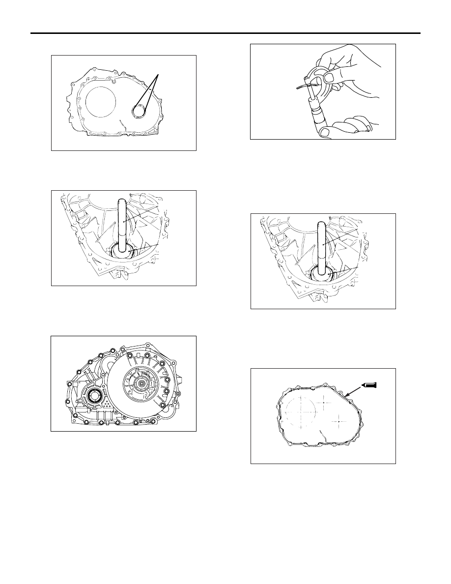
62.Place two pieces of about 10mm long, 3mm 

diameter solder on the converter housing at the 
locations indicated in the drawing.

63.Use the special tools to drive the outer race into 

position.

• Installer adapter (MB990935)

• Handle (MB990938)

64.Install the converter housing on the transmission 

case without applying FIPG. Tighten the mounting 
bolts to the specified torque of 48 

± 6 N⋅m.

65.Remove the bolts and converter housing, and 

take out the solder pieces.

66.Use a micrometer to measure the thickness of the 

crashed solder.

67.Select a spacer of the thickness equivalent to the 

micrometer reading plus the standard preload 
value.

Standard preload value: 0.045 

 0.105mm

68.Install the spacer selected in step 67. into the 

converter housing and drive the outer race into 
position using the special tools.

• Installer adapter (MB990935)

• Handle (MB990938)

69.Apply an approx. 1.6 mm diameter bead of 

from-in-place gasket (FIPG) to the converter 
housing along its circumference as shown in the 
drawing.

Specified sealant:

Mitsubishi genuine sealant Part No. MD974421 

or equivalent

AK201992

Solder

AB

AK100362 AE

MB990938

MB990935

AK301084

AK301249

AK100362 AE

MB990938

MB990935

AK201994

TRANSMISSION

AUTOMATIC TRANSMISSION OVERHAUL

23B-37

70.Install the O-rings (two pieces).

71.Install the converter housing and tighten the 

mounting bolts to the specified torque of 48 

± 6 

N

⋅m.

72.Install the manual control lever shaft and parking 

pawl rod.

73.Install the manual control lever shaft roller.
74.Fit a new seal ring to each accumulator piston.

NOTE: All the four accumulator pistons and seal 
rings are identical.

75.Identify the accumulator spring for each 

accumulator and install it in the correct hole in the 
transmission case together with the piston.
NOTE: The accumulator springs are identified as 
shown in the table below.

76.Install the strainer and second brake retainer oil 

seal as shown in the drawing.

77.Fit a new O-ring into the groove in the solenoid 

valve harness connector.

AK300232

AK301084

AK300520

No. Accumulator spring

Blue ink marking

1

For low-reverse brake

No marking

2

For underdrive clutch

Half of surface

3

For second brake

Entire surface

4

For overdrive clutch

No marking

AK301313

1

2

3

4

AB

AK300229AC

2

1

3

4

AK300228

Strainer

AC

Second brake
retainer oil seal

TRANSMISSION

AUTOMATIC TRANSMISSION OVERHAUL

23B-38

78.Insert the solenoid valve harness connector into 

the hole in the transmission case from inside the 
case. After making sure that the connector is 
positioned as shown in the drawing, fit the snap 
ring snugly into the connector groove.

79.Install the steel balls one each in the two holes on 

the top of the valve body (outside valve body).

80.Install the valve body and gasket. Make sure that 

the pin of the manual valve is in place in the 
detent plate groove in the manual control lever 
shaft.

81.Install the valve body mounting bolts and tighten 

them to the specified torque of 11 

± 1 N⋅m.

82.Install the oil temperature sensor and them 

connect the connector to the valve body.

83.Install the manual control shaft detent and tighten 

its mounting bolt to the specified torque of 6.0 

± 

1.0 N

⋅m.

AK300227AC

Snap ring

Connector

AK300226AC

Steel balls

AK300225

No. Solenoid valve Wire 

colour

Connector 
housing colour

1

Underdrive 
solenoid valve

White/re
d/red

Black

2

Overdrive 
solenoid valve

Orange/r
ed

Black

3

Low-reverse 
solenoid valve

Brown/y
ellow

Milky white

4

Second 
solenoid valve

Blue/red
/red

Milky white

5

Damper clutch 
control solenoid 
valve

Blue/yell
ow/yello
w

Black

AK300224AC

Fluid temperature sensor

1

4

5

2

3

AK300222AC

Manual control shaft detent

AK301264AB

TRANSMISSION

AUTOMATIC TRANSMISSION OVERHAUL

23B-39

84.Apply an approx. 2.5 mm diameter bead of 

from-in-place gasket (FIPG) to the valve body 
cover along its circumference as shown in the 
drawing.

Specified sealant:

Mitsubishi genuine sealant Part No. MD974421 

or equivalent

85.Install the valve body cover and tighten its 

mounting bolts to the specified torque of 11 

± 1 

N

⋅m.

86.Install the sealing cap.

87.Install the inhibitor switch and the manual control 

lever, and tighten its mounting bolts to the 
specified torque of 23 

± 3 N⋅m.

88.Install the input shaft speed sensor and output 

shaft speed sensor.

89.Press Face "A" of the air breather to be on the 

same plane as the Face "B" of the transmission 
case as shown in the drawing.

90.Coat both sides of the four new gaskets and the 

screw threads of the eyebolt with ATF, install the 
oil cooler feed tube, and then tighten the eyebolt 
to 24 

± 3 N⋅m.

91.Install a new O-ring on the oil filter tube and 

connect the tube to the valve body cover.

92.Install the oil level gauge.
93.Install the brackets.

AK300221

AK300220

AK300219AC

Inhibitor switch

Manual control lever

AK300218AC

Output shaft speed sensor

Input shaft speed sensor

AK203140 AC

A

A

B

B

AK201997

A

AB


Content   ..  968  969  970  971   ..