Mitsubishi Grandis. Manual - part 934
 

  Index      Mitsubishi     Mitsubishi Grandis - service repair manual


Search            


Content   ..  932  933  934  935   ..


Mitsubishi Grandis. Manual - part 934


TROUBLESHOOTING

TRACTION CONTROL/ACTIVE STABILITY CONTROL SYSTEM

35C-61

DIAGNOSIS CODE SET CONDITIONS

This diagnosis code is set if the master cylinder 
pressure sensor is defective.

PROBABLE CAUSES

The most likely cause for this diagnosis code to set 
is:

• Malfunction of the hydraulic unit (integrated with 

TCL/ASC-ECU)

DIAGNOSIS

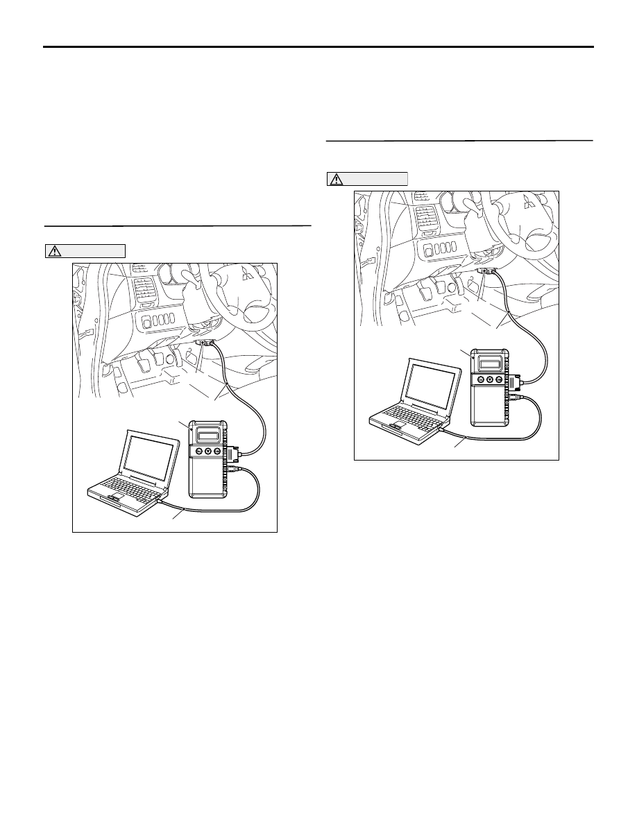
STEP 1. MUT-III CAN bus diagnostics

CAUTION

Before connecting or disconnecting the MUT-III, 
turn the ignition switch to the "LOCK" (OFF) 
position.
(1) Connect MUT-III to the 16-pin diagnosis 

connector.

(2) Turn the ignition switch to the "ON" position.
(3) Diagnose the CAN bus line.
(4) Turn the ignition switch to the "LOCK" (OFF) 

position.

Q: Is the check result normal?

YES : 

Go to Step 2.

NO : 

Repair the CAN bus line (Refer to GROUP 
54D, CAN bus line Diagnostic flow 

P.54D-9

). Then go to Step 2.

STEP 2. Check whether the diagnosis code is 
reset.

CAUTION

Before connecting or disconnecting the MUT-III, 
turn the ignition switch to the "LOCK" (OFF) 
position.
(1) Turn the ignition switch to the "ON" position.
(2) Erase the diagnosis code.
(3) Turn the ignition switch to the "LOCK" (OFF) 

position.

(4) Turn the ignition switch to the "ON" position.
(5) Check if the diagnosis code is set.
(6) Turn the ignition switch to the "LOCK" (OFF) 

position.

Q: Is code No.C1361 or C1364 set?

YES : 

Replace the hydraulic unit (integrated with 

TCL/ASC-ECU). 

NO : 

The procedure is complete.

AC302297

AC310120

AB

MB991827

16-pin

MB991910

MB991824

AC302297

AC310120

AB

MB991827

16-pin

MB991910

MB991824

TROUBLESHOOTING

TRACTION CONTROL/ACTIVE STABILITY CONTROL SYSTEM

35C-62

Code No.C1366: Lateral G-sensor (seizure or abnormal output signal)
Code No.C1371: Yaw rate sensor (seizure or abnormal output signal)

CAUTION

If there is any problem in the CAN bus lines, an 
incorrect diagnosis code may be set. Prior to this 
diagnosis, diagnose the CAN bus lines.

OPERATION

• The G and yaw rate sensor is energized by the 

TCL/ASC-ECU and the G and yaw rate sensor 
terminal 1.

• The G and yaw rate sensor output signal is sent 

to the TCL/ASC-ECU via the private CAN bus 
line.

DIAGNOSIS CODE SET CONDITIONS

These codes are set at the following cases:

Code No.C1366: Lateral G-sensor (seizure or 

abnormal output signal)

• Lateral acceleration value from the sensor is 

abnormal, or the value does not fluctuate during 
driving.

Code No.C1371: Yaw rate G-sensor (seizure or 

abnormal output signal)

• Yaw rate value from the sensor is abnormal, or 

the value does not fluctuate during driving.

PROBABLE CAUSES

• Malfunction of the G and yaw rate sensor

• Incorrect installing of G and yaw rate sensor

• Steering wheel sensor-related abnormality

• Damaged wiring harness or connector

• Malfunction of the hydraulic unit (integrated with 

TCL/ASC-ECU)

TCL/ASC-ECU

Wire colour code
B : Black     LG : Light green     G : Green     L : Blue     W : White     Y : Yellow     SB : Sky blue
BR : Brown     O : Orange     GR : Gray     R : Red     P : Pink     V : Violet   

G AND YAW 
LATE SENSOR

G and Yaw Late Sensor Circuit

TROUBLESHOOTING

TRACTION CONTROL/ACTIVE STABILITY CONTROL SYSTEM

35C-63

DIAGNOSIS

STEP 1. MUT-III CAN bus diagnostics

CAUTION

Before connecting or disconnecting the MUT-III, 
turn the ignition switch to the "LOCK" (OFF) 
position.
(1) Connect MUT-III to the 16-pin diagnosis 

connector.

(2) Turn the ignition switch to the "ON" position.
(3) Diagnose the CAN bus line.
(4) Turn the ignition switch to the "LOCK" (OFF) 

position.

Q: Is the check result normal?

YES : 

Go to Step 3.

NO : 

Repair the CAN bus line (Refer to GROUP 
54D, CAN bus line Diagnostic flow 

P.54D-9

). Then go to Step 2.

STEP 2. Check whether the diagnosis code is 
reset.

CAUTION

Before connecting or disconnecting the MUT-III, 
turn the ignition switch to the "LOCK" (OFF) 
position.
(1) Turn the ignition switch to the "ON" position.
(2) Erase the diagnosis code.
(3) Turn the ignition switch to the "LOCK" (OFF) 

position.

(4) Turn the ignition switch to the "ON" position.
(5) Check if the diagnosis code is set.
(6) Turn the ignition switch to the "LOCK" (OFF) 

position.

Q: Is code No.C1366 or 1371 set? 

YES : 

Go to Step 3.

NO : 

The procedure is complete.

AC302297

AC310120

AB

MB991827

16-pin

MB991910

MB991824

AC302297

AC310120

AB

MB991827

16-pin

MB991910

MB991824

TROUBLESHOOTING

TRACTION CONTROL/ACTIVE STABILITY CONTROL SYSTEM

35C-64

STEP 3. MUT-III data list

CAUTION

Before connecting or disconnecting the MUT-III, 
turn the ignition switch to the "LOCK" (OFF) 
position.
(1) Connect the MUT-III to the 16-pin diagnosis 

connector.

(2) Turn the ignition switch to the "ON" position.
(3) Use MUT-III to read the following data list.

Item 31: Lateral G sensor

• Acceleration should measure nearly 0G when 

the vehicle is stopped at a level surface.

• Acceleration should change within the range 

of -1.7 

− 1.7 G during running.

Item 33: Yaw rate sensor

• Angular velocity should measure nearly 0 

deg/s (-3 

−3 deg/s) when the vehicle is 

stopped at a level surface.

• Angular velocity should change within the 

range of -75 

−75 deg/s during running.

Q: Is the check result normal?

YES : 

Then go to step 9.

NO : 

Go to Step 4.

STEP 4. Voltage measurement at G and yaw rate 
sensor connector C-117.

(1) Disconnect the G and yaw rate sensor connector 

C-117, and measure at the harness side 
connector.

(2) Turn the ignition switch to the "ON" position.
(3) Measure the voltage between terminal 1 and 

AC302297

AC310120

AB

MB991827

16-pin

MB991910

MB991824

AC313186

AB

Connector: C-117
<L.H.drive vehicles>

C-117

C-117 Harness connector
(harness side)

AC313188AB

Connector: C-117
<R.H.drive vehicles>

C-117

C-117 Harness connector
(harness side)


Content   ..  932  933  934  935   ..