Mitsubishi Grandis. Manual - part 932
TROUBLESHOOTING
TRACTION CONTROL/ACTIVE STABILITY CONTROL SYSTEM
35C-53
<RH drive vehicles>
CAUTION
If there is any problem in the CAN bus lines, an
incorrect diagnosis code may be set. Prior to this
diagnosis, diagnose the CAN bus lines.
OPERATION
The "ON" signal when the brake pedal is pressed or
the "OFF" signal when the brake pedal is released is
input to the TCL/ASC-ECU (terminal 41).
DIAGNOSIS CODE SET CONDITIONS
Diagnosis code No.1340 is set in the following cases:
• Stop lamp switch is not operating properly and
remains ON state and vehicle speed exceeds
20km/h for more than 6 minutes.
• Stop lamp switch system harness is damaged
and no signal is input to TCL/ASC-ECU.
PROBABLE CAUSES
The most likely causes for this diagnosis code to set
are:
• Malfunction of the stop lamp switch
• Incorrect positioning of stop lamp switch
• Malfunction of bypass resistance integrated in
stop lamp switch
• Damaged wiring harness or connector
• Malfunction of the hydraulic unit (integrated with
TCL/ASC-ECU)
AC313601
26
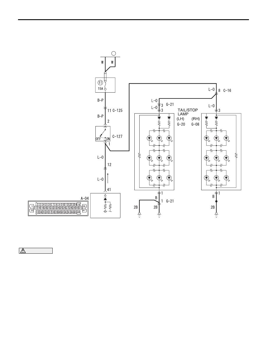
FUSIBLE
LINK
RELAY
BOX
STOP LAMP
SWITCH
TCL/ASC-ECU
Wire colour code
B : Black LG : Light green G : Green L : Blue W : White Y : Yellow SB : Sky blue
BR : Brown O : Orange GR : Gray R : Red P : Pink V : Violet
Stop Lamp Switch Circuit
AB