Mitsubishi Grandis. Manual - part 933


  Index      Mitsubishi     Mitsubishi Grandis - service repair manual


Search            


Content   ..  931  932  933  934   ..


Mitsubishi Grandis. Manual - part 933


TROUBLESHOOTING

TRACTION CONTROL/ACTIVE STABILITY CONTROL SYSTEM

35C-57

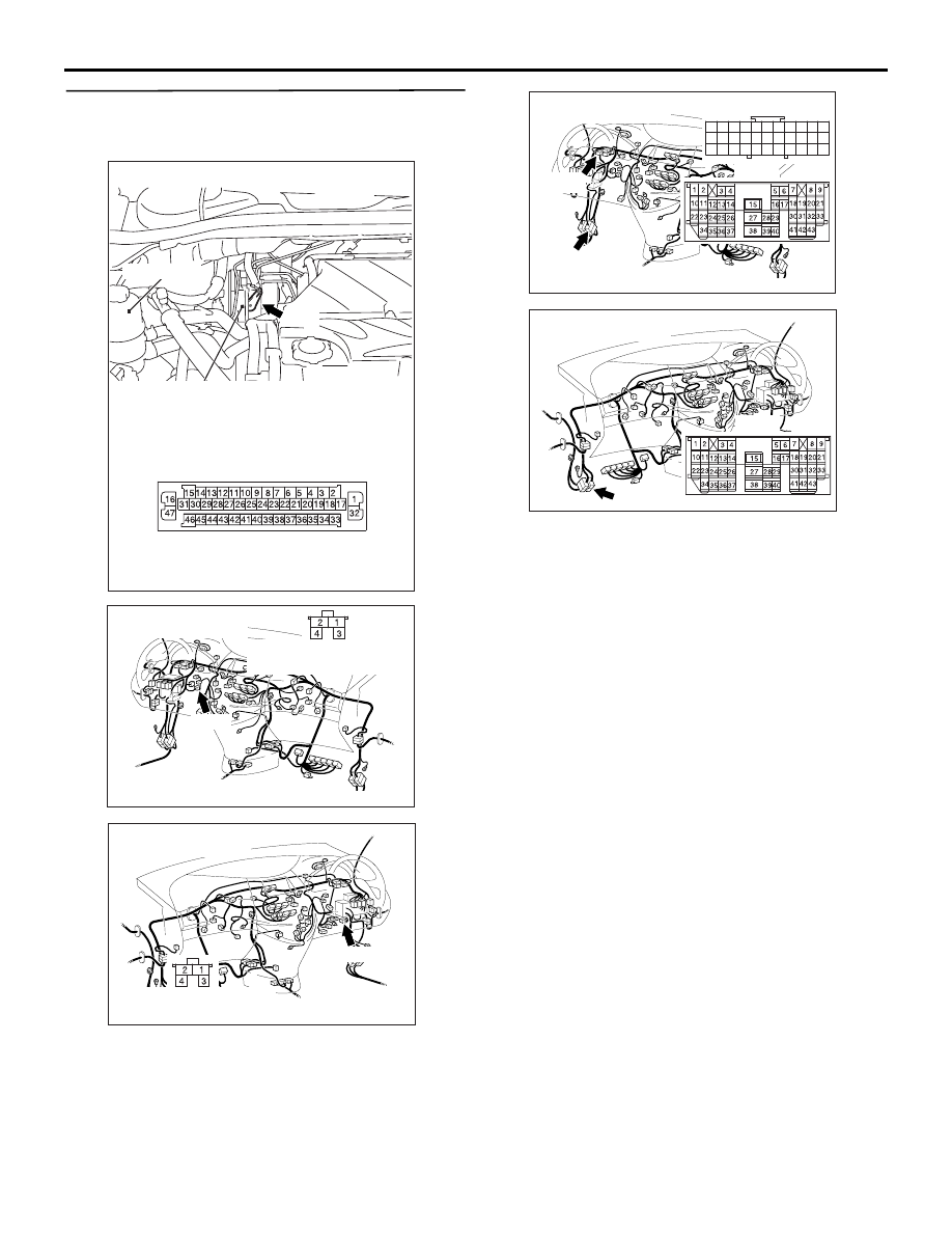
STEP 8. Check the harness wire between 
TCL/ASC-ECU connector A-04 terminal 41 and 
stop lamp switch connector C-127 terminal 1.

NOTE: 

After inspecting TCL/ASC-ECU connector A-04, 
intermediate connectors C-32 <L.H.drive vehicles>, 
C-124 and stop lamp switch connector C-127, 
inspect the wire. If any of these connectors is 
damaged, repair or replace it. Then go to Step 11.

Q: Is the check result normal?

YES : 

Disconnect the connection between the 

combination meter and the engine-A/T-ECU 
or the engine-ECU, and then go to Step 9.

NO : 

Go to Step 11.

AC312621

Oil reservoir

Connector: A-04

AB

A-04

Hydraulic unit
(with built-in TCL/ASC-ECU)

A-04 Harness connector
(harness side)

AC312624AD

Connector: C-127
<L.H.drive vehicles>

C-127

C-127 Harness connector
(harness side)

AC312625AD

Connector: C-127
<R.H.drive vehicles>

C-127

C-127 Harness connector
(harness side)

AC312624

33

22

11

28

17

16

15

14

13

12

25

2324

2627

3

1 2

4 5

21

20

19

18
2930

32

31

7

6

8

10

9

AE

Connectors: C-32, C-124
<L.H.drive vehicles>

C-32

C-32

C-124

C-124

AC312625AE

Connector: C-124
<R.H.drive vehicles>

C-124

C-124

TROUBLESHOOTING

TRACTION CONTROL/ACTIVE STABILITY CONTROL SYSTEM

35C-58

STEP 9. Check the harness wire between stop 
lamp switch connector C-127 terminal 1 and stop 
lamp connector G-20 terminal 1 and stop lamp 
connector G-08 terminal 1.

TROUBLESHOOTING

TRACTION CONTROL/ACTIVE STABILITY CONTROL SYSTEM

35C-59

CAUTION

• The lamp circuit contains a diode. If the tester 

is connected with polarity reversed, the 
measurement resistance may vary.

• The measurement value varies according to 

the tester voltage. 

NOTE: After inspecting intermediate connectors 
C-16, C-32 <L.H.drive vehicles>, G-21, stop lamp 
switch connector C-127 and atop lamp connector 
G-08 and G-20, inspect the wire. If any of these 
connectors is damaged, repair or replace it. Then go 
to Step 11
.

Q: Is the check result normal?

YES : 

Check the combination meter and the 

engine-A/T-ECU or the engine-ECU.

NO : 

Repair it and then go to Step 10.

AC313603AB

Connectors: C-32, C-16, C-127, G-08, G-20,
G-21 <L.H.drive vehicles>

C-127

C-127 Harness
connector
(harness side)

G-08

G-20

G-21

G-08/G-20
Harness connector

C-32

C-16

G-21

C-32

C-16

AC313604AB

Connectors: C-16, C-127, G-08, G-20, G-21
<R.H.drive vehicles>

C-127

C-127 Harness
connector
(harness side)

G-08

G-20

G-21

G-08/G-20
Harness connector

C-16

G-21

C-16

TROUBLESHOOTING

TRACTION CONTROL/ACTIVE STABILITY CONTROL SYSTEM

35C-60

STEP 10. Check whether the diagnosis code is 
reset.

Check again if the diagnosis code is set.
(1) Turn the ignition switch to the "ON" position.
(2) Erase the diagnosis code.
(3) Turn the ignition switch to the "LOCK" (OFF) 

position.

(4) Turn the ignition switch to the "ON" position.
(5) Check if the diagnosis code is set.
(6) Turn the ignition switch to the "LOCK" (OFF) 

position.

Q: Is code No.C1340 set?

YES : 

Replace the hydraulic unit (integrated with 

TCL/ASC-ECU). Then go to Step 11.

NO : 

It can be assumed that this malfunction is 
intermittent. Refer to GROUP 00, How to 
Use Troubleshooting/Inspection Service 
Points 

− How to Cope with Intermittent 

Malfunction 

P.00-5

.

STEP 11. Check whether the diagnosis code is 
reset.

Check again if the diagnosis code is set.
(1) Turn the ignition switch to the "ON" position.
(2) Erase the diagnosis code.
(3) Turn the ignition switch to the "LOCK" (OFF) 

position.

(4) Turn the ignition switch to the "ON" position.
(5) Drive the vehicle at 20km/h or more for 6 minutes 

or more. (there is no need to drive continuously.)

(6) Stop the vehicle with braking at 40km/h or more.
(7) Check if the diagnosis code is set.
(8) Turn the ignition switch to the "LOCK" (OFF) 

position.

Q: Is code No.C1340 set?

YES : 

Go to Step 1.

NO : 

The procedure is complete.

Code No.C1361: Abnormal pressure sensor characteristics
Code No.C1364: Pressure sensor malfunction

CAUTION

If there is any problem in the CAN bus lines, an 
incorrect diagnosis code may be set. Prior to this 
diagnosis, diagnose the CAN bus lines.

CAUTION

Whenever the ECU is replaced, ensure that the 
CAN bus lines are normal.

OPERATION

The master cylinder pressure sensor is incorporated 
in the hydraulic unit. When the brake pedal is 
depressed, the sensor detects the fluid pressure in 
the master cylinder, and converts it to voltage signal.

AC302297

AC310120

AB

MB991827

16-pin

MB991910

MB991824

AC302297

AC310120

AB

MB991827

16-pin

MB991910

MB991824


Content   ..  931  932  933  934   ..