Mitsubishi Grandis. Manual - part 825


  Index      Mitsubishi     Mitsubishi Grandis - service repair manual


Search            


Content   ..  823  824  825  826   ..


Mitsubishi Grandis. Manual - part 825


MARK

EXTERIOR

51-35

INSPECTION

M1511019100697

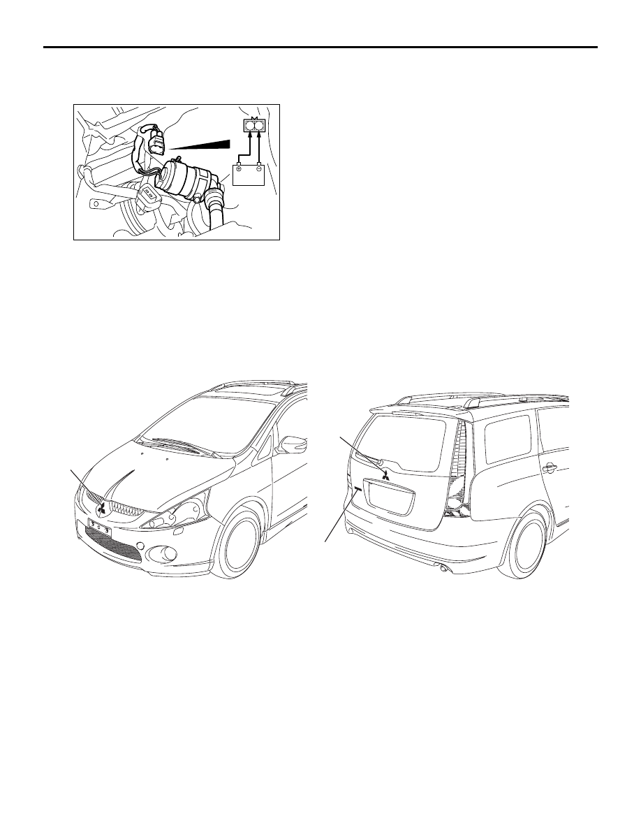
HEADLAMP WASHER MOTOR CHECK

1. Remove the headlamp washer motor connector.
2. Check to see that the water is vigorously sprayed 

when connecting the positive battery terminal to 
terminal number 1 and terminal number 2 to the 
negative battery terminal.

MARK

REMOVAL AND INSTALLATION

M1511011800409

INSTALLATION SERVICE POINT
>>A<< MARK APPLICATION

1. Installation position 

Attach each mark to the position shown in the 
illustration.

AC311181

1 2

AC310966

1

2

3

AB

Removal

1. Front three-diamond mark

>>A<<

2. Rear three-diamond mark

>>A<<

3. Grandis mark

DOOR MIRROR

EXTERIOR

51-36

2. Installation procedure

(1) Use 3M ATD Part number 8906 or equivalent 

to clean the mark installation surfaces on the 
body.

CAUTION

When attaching the marks, the ambient 
temperature should be 20 

 38°C and the air 

should be completely free of dust. If the ancient 
temperature is lower than 20

°C, the marks and 

the places on the vehicle body where the marks 
are to be attached should be heated to 20 

 38°C.

(2) Peel off the protection sheet on the back of the 

marks to paste it on the installation position.

DOOR MIRROR

SERVICE SPECIFICATION

M1511000300455

TROUBLESHOOTING

DIAGNOSIS TROUBLESHOOTING FLOW

M1511014600136

Refer to GROUP 00, How to Use 
Troubleshooting/Inspection Service Points 

P.00-5

.

AC302265 AB

16.5 mm

Rear three-diamond mark

Centre line of vehicle

Rear three-diamond mark 

Tailgate garnish

AC302288 AB

160 mm

Grandis mark

Grandis mark

Tailgate panel terminal

Application tape

Item

Standard value

Heated door mirror operation current 

7.5 

± 1.1

DOOR MIRROR

EXTERIOR

51-37

TROUBLE SYMPTOM CHART

M1511015000148

NOTE: The electric folding door mirrors are 
controlled by the Smart Wiring System (SWS). For 
troubles relating to the electric folding door mirrors, 
refer to GROUP 54B - Troubleshooting 

P.54B-74

 or 

GROUP 54C - Troubleshooting 

P.54C-44

.

INSPECTION PROCEDURE 1: All Heated Door Mirrors do not Operate

Symptom

Inspection 
procedure

Reference 
page

Troubles relating to electric folding door mirrors

-

P.54B-74

All heated door mirrors do not operate

1

P.51-37

The right or left heated door mirror does not operate

2

P.51-39

Wire colour code
B : Black     LG : Light green     G : Green     L : Blue     W : White     Y : Yellow     SB : Sky blue
BR : Brown     O : Orange     GR : Gray     R : Red     P : Pink     V : Violet   

REAR WINDOW
DEFOGGER RELAY

REAR WINDOW
DEFOGGER RELAY

DOOR
MIRROR
ASSEMBLY (RH)

DOOR
MIRROR
ASSEMBLY (LH)

MIRROR 
HEATER

MIRROR 
HEATER

Heated door mirror circuit

DOOR MIRROR

EXTERIOR

51-38

COMMENTS ON TROUBLE SYMPTOM

The heated door mirrors should work for 
approximately 11 minutes  when the rear defogger 
switch is turned on. If the mirror heater does not work 
for the specified period, the defogger relay circuit 
(heated door mirror power supply circuit) may be 
defective.

POSSIBLE CAUSES

• Damaged harness wires and connectors

DIAGNOSIS PROCEDURE

Step 1. Check the rear window defogger.

Check that the rear defogger system should work 
normally. (Refer to GROUP 54A, Rear window 
defogger inspection 

P.54A-176

.)

Q: Is the check result normal?

YES : 

Go to Step 2.

NO : 

Carry out the troubleshooting for the rear 
window defogger. (Refer to GROUP 55, 
Troubleshooting 

P.55-43

.)

Step 2. Connector check: C-205 junction block 
connector.

Q: Is the check result normal?

YES : 

The trouble can be an intermittent 

malfunction (Refer to GROUP 00, How to 
use Troubleshooting/inspection Service 
Points 

− How to Cope with Intermittent 

Malfunction 

P.00-5

).

NO : 

Repair the defective connector.

AC311691

21

7

16 15

17

18

20 19

1

2

3

4

5

6

23 22

24

25

28

26

27

9

8

10

11

14

12

13

Harness side

AB

Connector: F-205

Junction block (Front view)


Content   ..  823  824  825  826   ..