Mitsubishi Grandis. Manual - part 826
DOOR MIRROR
EXTERIOR
51-39
INSPECTION PROCEDURE 2: Right or Left Heated Door Mirror does not Operate
COMMENTS ON TROUBLE SYMPTOM
If either of the heated door mirrors does not work, the
door mirror assembly may be defective.
POSSIBLE CAUSES
• Malfunction of the door mirror assembly
• Damaged harness wires and connectors
DIAGNOSIS PROCEDURE
Step 1. Verify the operation of each heated door
mirror.
Q: Which door mirror does not heat?
Door mirror (RH) :
Go to Step 2.
Door mirror (LH) :
Go to Step 10.
Step 2. Connector check: F-13-1 and F-13-2 door
mirror (RH) heater element connectors
Q: Is the check result normal?
Wire colour code
B : Black LG : Light green G : Green L : Blue W : White Y : Yellow SB : Sky blue
BR : Brown O : Orange GR : Gray R : Red P : Pink V : Violet
REAR WINDOW
DEFOGGER RELAY
REAR WINDOW
DEFOGGER RELAY
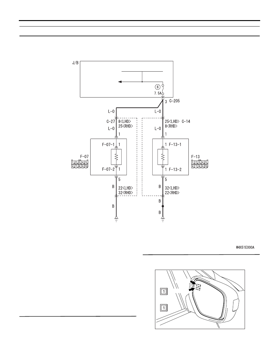
DOOR
MIRROR
ASSEMBLY (RH)
DOOR
MIRROR
ASSEMBLY (LH)
MIRROR
HEATER
MIRROR
HEATER
Heated door mirror circuit
AC303175
E-13-1
E-13-2
E-13-1
E-13-2
AB