Mitsubishi Grandis. Manual - part 804


  Index      Mitsubishi     Mitsubishi Grandis - service repair manual


Search            


Content   ..  802  803  804  805   ..


Mitsubishi Grandis. Manual - part 804


EMISSION CONTROL <MPI>

ENGINE AND EMISSION CONTROL

17-57

EMISSION CONTROL <MPI>

GENERAL INFORMATION

M1173000100552

The emission control system consists of the following 
subsystems:

• Crankcase emission control system

• Evaporative emission control system

• Exhaust emission control system

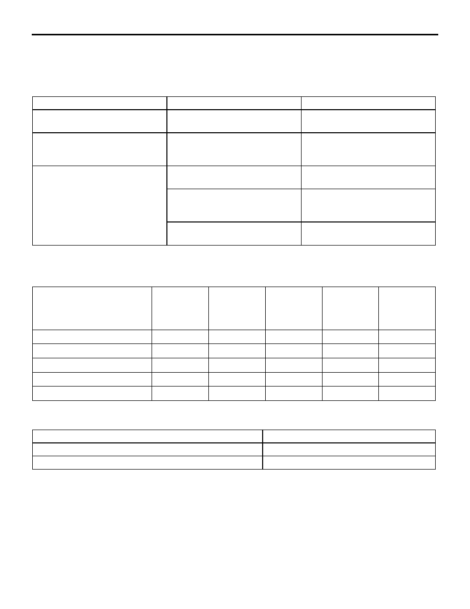
EMISSION CONTROL DEVICE 
REFERENCE TABLE

M1173006600191

SERVICE SPECIFICATION(S)

M1173000300459

Items

Name

Specification

Crankcase emission control 
system

Positive crankcase ventilation 
(PCV) valve

Variable flow type
(Purpose: HC reduction)

Evaporative emission control 
system

Canister
Purge control solenoid valve

Equipped
Duty cycle type solenoid valve
(Purpose: HC reduction)

Exhaust emission control system

Air-fuel ratio control device - MPI 
system

Oxygen sensor feedback type 
(Purpose: CO, HC, NOx reduction)

Exhaust gas recirculation system 

• EGR valve

Equipped
Steeper motor type
(Purpose: NOx reduction)

Catalytic converter

Monolith type
(Purpose: CO, HC, NOx reduction)

Related parts

Crankcase 
emission 
control 
system

Evaporative 
emission 
control 
system

Air/fuel ratio 
control 
system

Catalytic 
converter

Exhaust gas 
recirculation 
system

PCV valve

×

Purge control solenoid valve

×

MPI system component

×

×

Catalytic converter

×

EGR valve (Steeper motor) 

×

Items

Standard value

Purge control solenoid valve coil resistance (at 20

°C) Ω

30 

− 34

EGR valve coil resistance (at 20

°C) Ω

20 

− 24

EMISSION CONTROL <MPI>

ENGINE AND EMISSION CONTROL

17-58

SPECIAL TOOL

M1173000600201

VACUUM HOSE

VACUUM HOSE PIPING DIAGRAM

M1173000900525

Tool

Number

Name

Use

MD991658

Test harness

EGR valve (Steeper moter) 
CHECK

MD998770

Oxygen sensor wrench

Removal and installation of 
oxygen sensor

MB991658

AK305675

Cylinder 1, 4 oxygen
sensor (front)

Cylinder 2, 3 oxygen
sensor (front)

Cylinder 1, 4 oxygen
sensor (rear)

Cylinder 2, 3 oxygen
sensor (rear)

Catalytic

converter

Catalytic
converter

From
fuel pump

Canister

EGR valve

(stepper motor)

Purge control

solenoid valve

Air

AB

To
fuel tank

Fuel pressure
regulator

PCV valve

Air cleaner

EMISSION CONTROL <MPI>

ENGINE AND EMISSION CONTROL

17-59

VACUUM CIRCUIT DIAGRAM

M1173007100382

VACUUM HOSE CHECK

M1173007300160

1. Using the piping diagram as a guide, check to be 

sure that the vacuum hoses are correctly 
connected.

2. Check the connection condition of the vacuum 

hoses, (removed, loose, etc.) and check to be 
sure that there are no bends or damage.

VACUUM HOSE INSTALLATION

M1173007200118

1. When connecting the vacuum hoses, they should 

be securely inserted onto the nipples.

2. Connect the hoses correctly, using the vacuum 

hose piping diagram as a guide.

CRANKCASE EMISSION CONTROL 
SYSTEM

GENERAL INFORMATION (CRANKCASE 
EMISSION CONTROL SYSTEM)

M1173005000420

The crankcase emission control system prevents 
blow-by gases from escaping inside the crankcase 
into the atmosphere.
Fresh air is sent from the air cleaner into the 
crankcase through the breather hose.
The air becomes mixed with the blow-by gases 
inside the crankcase.
The blow-by gas inside the crankcase is drawn into 
the intake manifold through the positive crankcase 
ventilation (PCV) valve.
The PCV valve lifts the plunger according to the 
intake manifold vacuum so as to regulate the flow of 
blow-by gas properly.
In other words, the blow-by gas flow is regulated 
during low load engine operation to maintain engine 
stability, while the flow is increased during high load 
operation to improve the ventilation performance.

AK305676

B

From 
air 
cleaner

To
combustion
chamber

Throttle body

B

B

B

AB

Intake manifold

B

Purge
control 
solenoid
valve

Canister

Vacuum hose colour
B: Black

Fuel
pressure 
regulator

EMISSION CONTROL <MPI>

ENGINE AND EMISSION CONTROL

17-60

SYSTEM DIAGRAM

COMPONENT LOCATION (CRANKCASE 
EMISSION CONTROL SYSTEM)

M1173007400305

POSITIVE CRANKCASE VENTILATION 
SYSTEM CHECK

M1173001100221

1. Remove the ventilation hose from the PCV valve.
2. Remove the PCV valve from the rocker cover.
3. Reinstall the PCV valve at the ventilation hose.

4. Start the engine and run at idle.

5. Place a finger at the opening of the PCV valve 

and check that vacuum of the intake manifold is 
felt.
NOTE: At this moment, the plunger in the PCV 
valve moves back and forth.

6. If vacuum is not felt, clean the PCV valve or 

replace it.

AK305677AB

Air cleaner

Air

Ventilation hose

Breather hose

PCV valve

AK302826

PCV valve

AC

AK300021

PCV valve

AC


Content   ..  802  803  804  805   ..