Mitsubishi Grandis. Manual - part 805


  Index      Mitsubishi     Mitsubishi Grandis - service repair manual


Search            


Content   ..  803  804  805  806   ..


Mitsubishi Grandis. Manual - part 805


EMISSION CONTROL <MPI>

ENGINE AND EMISSION CONTROL

17-61

POSITIVE CRANKCASE VENTILATION 
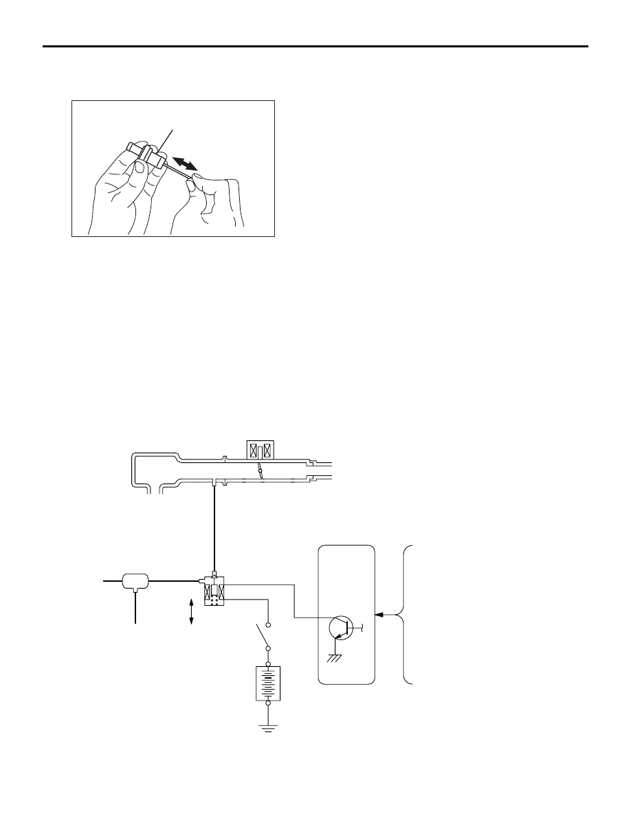
(PCV) VALVE CHECK

M1173001200217

1. Insert a thin rod into the PCV valve from the side 

shown in the illustration (rocker cover installation 
side), and move the rod back and forth to check 
that the plunger moves.

2. If the plunger does not move, there is a clogging 

in the PCV valve. In this case, clean or replace 
the PCV valve.

EVAPORATIVE EMISSION CONTROL 
SYSTEM

GENERAL INFORMATION (EVAPORATIVE 
EMISSION CONTROL SYSTEM)

M1173005100524

The evaporative emission control system prevents 
fuel vapours generated in the fuel tank from escaping 
into the atmosphere.
Fuel vapours from the fuel tank flow through the fuel 
tank pressure control valve and vapour pipe/hose to 
be stored temporarily in the canister.
When driving the vehicle, fuel vapours stored in the 
canister flow through the purge control solenoid 
valve and purge port and go into the intake manifold 
to be sent to the combustion chamber.
When the engine coolant temperature is low or when 
the intake air quantity is small (when the engine is at 
idle, for example), the engine control unit turns the 
purge solenoid off to shut off the fuel vapour flow to 
the intake manifold.
This does not only insure the driveability when the 
engine is cold or running under low load but also 
stabilize the emission level.

SYSTEM DIAGRAM

AK300022

PCV valve

AC

AK302829AB

Intake manifold

Canister

From
fuel
tank

OFF

ON

Purge
control
Solenoid
valve

Control
relay

Battery

Engine-ECU <M/T> or
Engine-A/T-ECU <A/T>

Air flow sensor

Engine coolant
temperature sensor

Intake air
temperature sensor

Barometric pressure sensor
(with engine-ECU <M/T>
or engine-A/T-ECU <A/T>)

EMISSION CONTROL <MPI>

ENGINE AND EMISSION CONTROL

17-62

COMPONENT LOCATION (EVAPORATIVE 
EMISSION CONTROL SYSTEM) 

M1173007500313

PURGE CONTROL SYSTEM CHECK

M1173001400437

1. Disconnect the vacuum hose (between purge 

control solenoid valve and intake manifold) from 
purge control solenoid valve and connect a hand 
vacuum pump to the nipple.

2. Plug the vacuum hose.
3. When the engine is cold or hot, apply a vacuum of 

53 kPa, and check the condition of the vacuum.

WHEN ENGINE IS COLD 
(ENGINE COOLANT TEMPERATURE: 40

°C OR 

LESS)

WHEN ENGINE IS HOT 
(ENGINE COOLANT TEMPERATURE: 80

°C OR 

HIGHER)

PURGE PORT VACUUM CHECK

M1173001500263

1. Disconnect the vacuum hose (between purge 

control solenoid valve and intake manifold) from 
the purge control solenoid valve and connect it to 
a hand vacuum pump.

2. Plug the nipple from which the vacuum hose was 

removed.

3. Start the engine.
4. Check that a fairly constant negative pressure is 

generated regardless of the engine speed.

5. If no negative pressure is generated, the port is 

probably blocked and should be cleaned.

PURGE CONTROL SOLENOID VALVE 
CHECK

M1173001700234

NOTE: When disconnecting the vacuum hose, 
always make a mark so that it can be reconnected at 
original position.

Engine condition

Normal condition

At idle

Vacuum is maintained.

3,000 r/min

Engine condition

Normal condition

At idle

Vacuum is maintained.

3,000 r/min (within 3 
minutes after engine 
starts)

Vacuum will leak.

AK302830

Purge control
solenoid valve

AC

AK302831

Plug

Vacuum hose

AB

AK302833

Plug

Vacuum hose

AB

AK100011

AC

Vac-
uum

Engine speed (r/min)

EMISSION CONTROL <MPI>

ENGINE AND EMISSION CONTROL

17-63

1. Disconnect the vacuum hose from the solenoid 

valve.

2. Disconnect the harness connector.

3. Connect a hand vacuum pump to nipple (A) of the 

solenoid valve (refer to the illustration at left).

4. Check airtightness by applying a vacuum with 

voltage applied directly from the battery to the 
purge control solenoid valve and without applying 
voltage.

5. Measure the resistance between the terminals of 

the solenoid valve.

Standard value: 30 

 34  (at 20°C)

AK100012 AC

Battery

A

AK100013

Battery voltage

Normal condition

Applied

Vacuum leaks

Not applied

Vacuum maintained

EMISSION CONTROL <MPI>

ENGINE AND EMISSION CONTROL

17-64

CANISTER REMOVAL AND INSTALLATION

M1173004200197

EXHAUST GAS RECIRCULATION 
(EGR) SYSTEM

GENERAL INFORMATION (EGR SYSTEM)

M1173005200435

The exhaust gas recirculation (EGR) system lowers 
the nitrogen oxide (NOx) emission level.
When the air/fuel mixture combustion temperature is 
high, a large quantity of nitrogen oxides (NOx) is 
generated in the combustion chamber.

Therefore, this system recirculates part of emission 
gas from the exhaust port of the cylinder head to the 
combustion chamber through the intake manifold to 
decrease the air/fuel mixture combustion 
temperature, resulting in reduction of NOx.
The EGR flow rate is controlled by the EGR valve so 
as not to decrease the driveability.

OPERATION

The EGR valve is being closed and does not 
recirculate exhaust gases under one of the following 
conditions.
Otherwise, the EGR valve is opened and recirculates 
exhaust gases.

• The engine coolant temperature is low.

• The engine is at idle.

• The throttle valve is widely opened.

Pre-removal and Post-installation Operation
Air Cleaner assembly Removal and Installation (Refer to 
GROUP 15, Air Cleaner 

P.15-3

).

AC310442

1

2

3

4

5

6

7

AB

<R.H. drive vehicles>

<L.H. drive vehicles>

Removal steps

1.

Purge hose connection

2.

Vapour hose

3.

Vent connector

4.

Vapour hose

5.

Hose clamp

6.

Canister

7.

Canister bracket


Content   ..  803  804  805  806   ..