Mitsubishi Grandis. Manual - part 803


  Index      Mitsubishi     Mitsubishi Grandis - service repair manual


Search            


Content   ..  801  802  803  804   ..


Mitsubishi Grandis. Manual - part 803


AUTO-CRUISE CONTROL

ENGINE AND EMISSION CONTROL

17-53

ON-VEHICLE SERVICE

AUTO-CRUISE CONTROL SWITCH 
CHECK

M1172001200098

AUTO-CRUISE CONTROL MAIN SWITCH 
CHECK

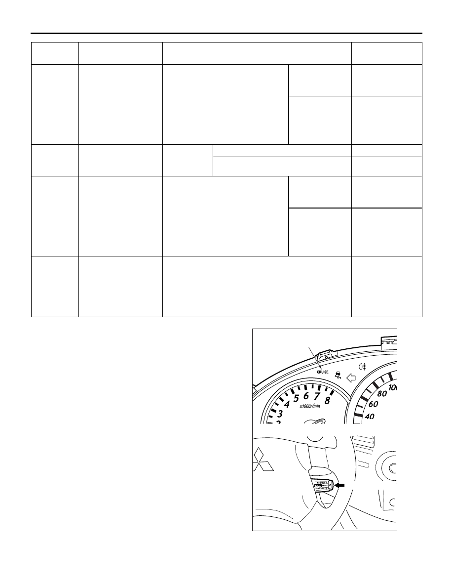
1. Turn the ignition switch to ON position.

2. Check that the auto-cruise control indicator lamp 

within the combination meter illuminates when the 
MAIN switch is switched ON.

113

Throttle position 
sensor (sub)

• Remove the intake air hose at 

the throttle body

• Disconnect the throttle position 

sensor, and then connect 
terminal numbers No. 3, No. 4, 
No. 5 and No. 6 with the use of 
the special tool (MB991658).

• Ignition switch: "ON"

Fully close the 
throttle valve 
with your finger

2.2 

− 2.8 V

Fully open the 
throttle valve 
with your finger

4.0 V or more

114

Accelerator pedal 
position sensor 
(main)

Ignition 
switch: "ON"

Release the accelerator pedal

0.9 

− 1.2 V

Depress the accelerator pedal.

4.0 V or more

115

Throttle position 
sensor (main)

• Remove the intake air hose at 

the throttle body

• Disconnect the throttle position 

sensor, and then connect 
terminal numbers No. 3, No. 4, 
No. 5 and No. 6 with the use of 
the special tool (MB991658).

• Ignition switch: "ON"

Fully close the 
throttle valve 
with your finger

0.3 

− 0.7 V

Fully open the 
throttle valve 
with your finger

4.0 V or more

132

Engine-ECU <M/T> 
or Engine-A/T-ECU 
<A/T> power supply 
voltage applied to 
throttle valve control 
servo

Ignition switch: "ON"

System voltage

Terminal 
No.

Check item

Check conditions

Normal 
condition

AC311410

AC311198

MAIN switch: ON

AB

Auto-cruise control
indicator lamp

AUTO-CRUISE CONTROL

ENGINE AND EMISSION CONTROL

17-54

AUTO-CRUISE CONTROL SETTING

1. Switch ON the MAIN switch.
2. Drive at the desired speed within the range of 

approximately 40 

− 200 km/h.

3. Push the auto-cruise control switch in the 

direction of arrow.

4. Check to be sure that when the switch is released 

the speed is the desired constant speed.
NOTE: If the vehicles speed decreases to 
approximately 15 km/h below the set speed 
because of climbing a hill for example, the 
auto-cruise control will be cancelled.

SPEED-INCREASE SETTING

1. Set to the desired speed.

2. Push the auto-cruise control switch in the 

direction of arrow.

3. Check to be sure that acceleration continues 

while the switch is hold, and that when it is 
released the constant speed at the time when it 
was released becomes the driving speed.
NOTE: Acceleration can be continued even if the 
vehicle speed has passed the high-speed limit 
(approximately 200 km/h). But the speed when 
the auto-cruise control switch is released will be 
recorded as the high-speed limit.

SPEED-REDUCTION SETTING

1. Set to the desired speed.

2. Push the auto-cruise control switch in the 

direction of arrow.

3. Check to be sure that deceleration continues 

while the switch is pressed, and that when it is 
released the constant speed at the time when it 
was released becomes the driving speed.
NOTE: When the vehicle speed reaches the low 
limit (approximately 40 km/h) during deceleration, 
the auto-cruise control will be cancelled.

RETURN TO THE SET SPEED BEFORE 
CANCELLATION AND AUTO-CRUISE 
CONTROL CANCELLATION

1. Set the auto-cruise speed control.
2. When any of the following operations are 

performed while at constant speed during 
auto-cruise control, check if normal driving is 
resumed and deceleration occurs.

(1) The auto-cruise control switch is pulled in the 

direction of arrow.

(2) The brake pedal is depressed.
(3) The selector lever is moved to the "N" range.

AC310956

AC310954

AC310955

AC310956

AC310957

AUTO-CRUISE CONTROL

ENGINE AND EMISSION CONTROL

17-55

3. When the auto-cruise control switch is pushed in 

the direction of arrow at a vehicle speed of 40 
km/h or higher, check if the vehicle speed returns 
to the speed before auto-cruise control driving 
was cancelled, and constant speed driving 
occurs.

4. When the MAIN switch is turned to OFF while 

driving at constant speed, check if normal driving 
is resumed and deceleration occurs. 

AUTO-CRUISE CONTROL SYSTEM 
COMPONENT CHECK

M1172001700424

AUTO-CRUISE CONTROL SWITCH 
CHECK

1. Remove the auto-cruise control switch. (Refer to 

P.17-56

).

2. Measure the resistance between the terminals 

when each of the SET, RESUME, CANCEL and 
MAIN switches is pressed. If the values measured 
at the time correspond to those in the table below, 
then there is no problem.

STOP LAMP SWITCH

1. Disconnect the connector.

2. Check for continuity between the terminals of the 

switch.

CLUTCH SWITCH <M/T>

Refer to GROUP 21A, On-vehicle Service 

− Clutch 

Pedal Switch Check and Adjustment 

P.21A-4

.

INHIBITOR SWITCH ("N" POSITION) 
<A/T>

Refer to GROUP 23A, On-vehicle Service 

− A/T 

Control Component Check 

P.23A-128

.

AC310956

1 2 3

AC203822AB

OFF

OFF

OFF

OFF

ON

ON

ON

ON

CAN

MAIN

RES

SET

2

3

Switch position

Specified condition

MAIN switch: OFF

Open circuit

MAIN switch: ON

Less than 2 

CANCEL switch: ON

Approximately 100 

RESUME switch: ON

Approximately 887 

SET switch: ON

Approximately 300 

Measurement 
conditions

Terminal 
connector of 
tester

Specified 
condition

When brake 
pedal is 
depressed. (for 
stop lamp 
circuit)

− 2

Less than 2 

− 4

Open circuit

When brake 
pedal is not 
depressed. (for 
auto-cruise 
control circuit)

− 2

Open circuit

− 4

Less than 2 

ACX01180AB

AUTO-CRUISE CONTROL

ENGINE AND EMISSION CONTROL

17-56

THROTTLE POSITION SENSOR

Refer to GROUP 13A, On-vehicle Service 

− Throttle 

Valve Control Servo Check 

P.13A-394

.

AUTO-CRUISE CONTROL

REMOVAL AND INSTALLATION

M1172001400360

WARNING

Before removal of the air bag module, refer to GROUP 52B, Service Precautions (

P.52B-7

and Driver’s, Front Passenger’s Air Bag Module(s) and Clock Spring (

P.52B-225

).

When removing and installing the steering wheel and air bag module assembly, do not let 
it bump against the air bag module.

AC311572

1

1.7 ± 0.2 N·m 

2

6

5

3

AB

7

8

4

Auto-cruise control switch removal 
steps

Air bag module (Refer to GROUP 
52B,  Driver’s, Front Passenger’s Air 
Bag Module(s) and Clock Spring 

P.52B-225

)

1. Auto-cruise control switch

Control unit removal

2. Engine-ECU <M/T> or 

Engine-A/T-ECU <A/T> (Refer to 
GROUP 13A, Engine-ECU and 
Engine-A/T-ECU 

P.13A-399

)

Sensor removal steps

3. Inhibitor switch <A/T>
4. Accelerator pedal (Refer to 

P.17-3

)

5. Vehicle speed sensor <M/T>
6. Throttle body assembly (Refer to 

GROUP 13A, Throttle body assembly 

P.13A-397

)

7. Stop lamp switch (Refer to GROUP 

35A, Brake peda

P.35A-12

)

8. Clutch switch <M/T> (Refer to 

GROUP 21A, Clutch pedal 

P.21A-5

)


Content   ..  801  802  803  804   ..