Mitsubishi Grandis. Manual - part 802


  Index      Mitsubishi     Mitsubishi Grandis - service repair manual


Search            


Content   ..  800  801  802  803   ..


Mitsubishi Grandis. Manual - part 802


AUTO-CRUISE CONTROL

ENGINE AND EMISSION CONTROL

17-49

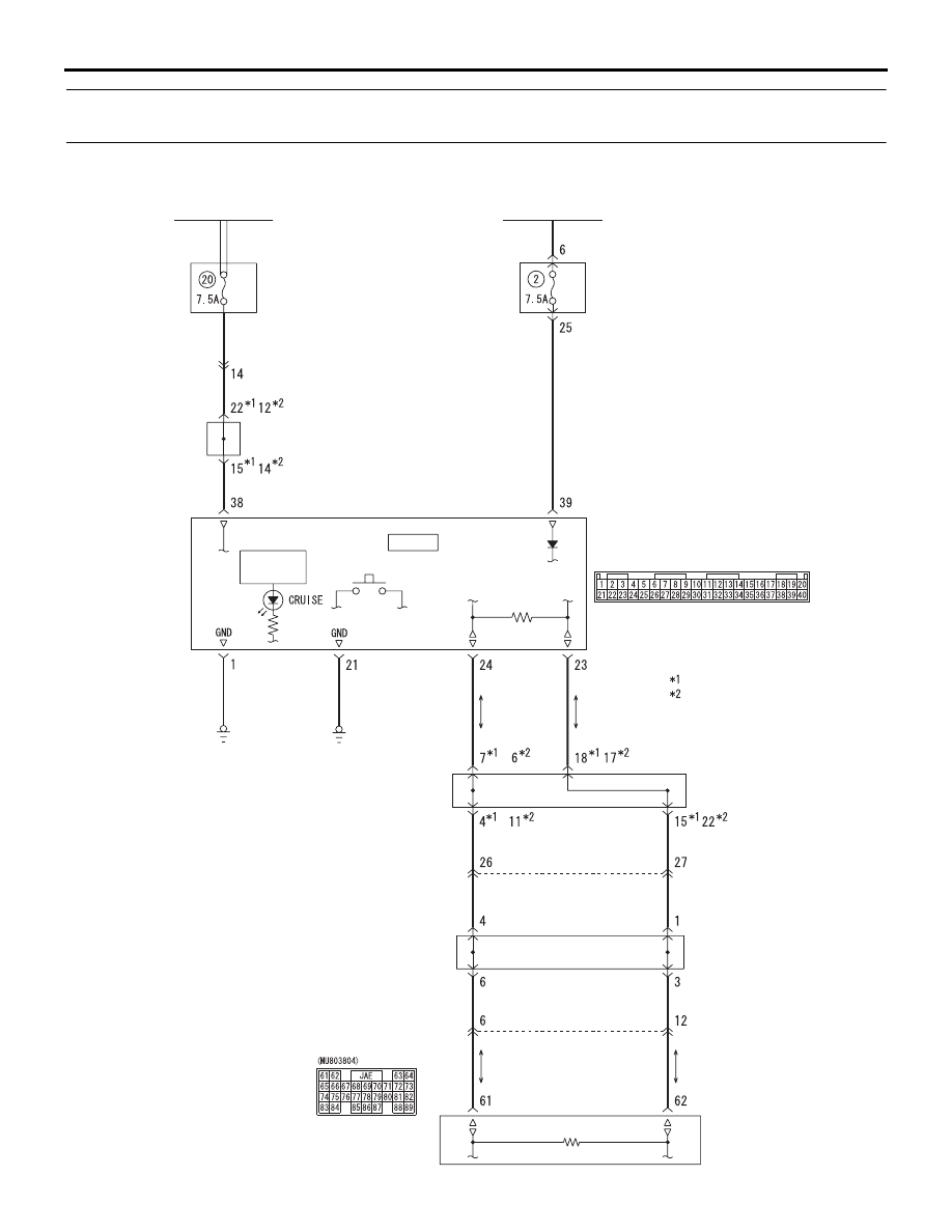
INSPECTION PROCEDURE 8: When the auto-cruise control MAIN switch is turned ON, the auto-cruise 
control indicator lamp does not illuminate. (However, the auto-cruise control system is normal).

Combination 
meter

C-02

Daytime
dipper
button

Dipper
circuit

CPU

Front-ECU
(Tail lamp relay)

Relay box

J/C (5)

J/C (CAN1)

J/C (CAN2)

Auto-cruise control indicator lamp drive circuit

C-202

C-205

G-W

C-125

C-125

C-09

A-07

A-16

C-112

C-31

G-W

Ignition switch (IG1)

J/B

B-W

L-B

G-W

B

B

R-L

R-L

R-L

B-L

B-L

R

R

B

B

B-L

NOTE

L.H. drive vehicles

R.H. drive vehicles

AC311469

Engine-ECU <M/T> or 
engine-A/T-ECU <A/T>

Wire colour code
B: Black  LG: Light green  G: Green  
L: Blue  W: White  Y: Yellow  SB: Sky blue  
BR: Brown  O: Orange  GR: Gray
R: Red  P: Pink  V: Violet

AUTO-CRUISE CONTROL

ENGINE AND EMISSION CONTROL

17-50

CIRCUIT OPERATION

The engine-ECU <M/T> or engine-A/T-ECU <A/T> 
detects MAIN switch "ON" signal to illuminate the 
auto-cruise control indicator lamp on the combination 
meter.

COMMENT

Connector(s), wiring harness in the CAN bus line 
between the engine-ECU <M/T> or engine-A/T-ECU 
<A/T> and the combination meter, power supply to 
the engine-ECU <M/T> or engine-A/T-ECU <A/T>, 
the combination meter, the engine-ECU <M/T> or 
engine-A/T-ECU <A/T> may be defective.

TROUBLESHOOTING HINTS

• Malfunction of the combination meter

• Malfunction of the connector.

• Malfunction of the harness.

• Malfunction of the engine-ECU <M/T>.

• Malfunction of the engine-A/T-ECU <A/T>.

DIAGNOSIS

STEP 1. MUT-III CAN bus diagnosis

• Using MUT-III, perform CAN busline diagnosis.

Q: Is the check result satisfactory?

YES : 

Go to Step 2 

NO : 

Repair the CAN bus lines (Refer to GROUP 
54D, Diagnosis-Can Bus Diagnostic Chart 

P.54D-16

). Then go to Step 4 .

STEP 2. MUT-III MPI diagnosis

• Using MUT-III, perform MPI diagnosis.

Q: Is diagnosis code U1108 set?

YES : 

Refer to GROUP 13A, MPI Diagnosis - 

Code No U1108: Combination Meter 
Time-Out 

P.13A-276

. Then go to Step 4 .

NO : 

Go to Step 3 .

STEP 3. Retest the system.

Q: Does the auto-cruise control indicator lamp 

illuminate when the MAIN switch is turned "ON"?

YES : 

It can be assumed that this malfunction is 

intermittent.

NO : 

Replace the engine-ECU <M/T> or 
engine-A/T-ECU <A/T> (Refer to GROUP 
13A, Engine-ECU and Engine-A/T-ECU 

P.13A-399

). Then go to Step 4 .

STEP 4. Retest the system.

Q: Does the auto-cruise control indicator lamp 

illuminate when the MAIN switch is turned "ON"?

YES : 

The procedure is complete.

NO : 

Return to Step 1 .

DATA LIST REFERENCE TABLE

M1172002400396

Item No.

Check item

Check condition

Normal condition

01

Auto-cruise 
control 
switch

MAIN

MAIN switch: ON

ON

MAIN switch: OFF

OFF

02

SET/COA
ST

MAIN switch: ON

SET switch: ON

ON

SET switch: OFF

OFF

03

RESUME/
ACCELER
ATING

RESUME switch: ON

ON

RESUME switch: OFF

OFF

04

CANCEL

CANCEL switch: ON

ON

CANCEL switch: OFF

OFF

05

Stop lamp switch (for 
stop lamp circuit)

Brake pedal: Depressed

ON

Brake pedal: Released

OFF

06

Stop lamp switch (for 
auto-cruise control 
circuit)

Brake pedal: Depressed

ON

Brake pedal: Released

OFF

AUTO-CRUISE CONTROL

ENGINE AND EMISSION CONTROL

17-51

07

Clutch switch <M/T>

Clutch pedal: Depressed

ON

Clutch pedal: Released

OFF

Inhibitor switch <A/T>

Selector lever: N or P position

ON

Selector lever: Other than N or P position

OFF

08

Accelerator switch (Idle 
switch)

Accelerator pedal: Depressed

OFF

Accelerator pedal: Released

ON

09

Auto-cruise control 
operation

Auto-cruise control: active

ON

Auto-cruise control: Inactive

OFF

10

Vehicle speed signal

Road test the vehicle

The speedometer and 
MUT-III display the 
same value.

11

Throttle position sensor 
(main)

• Remove the 

intake air hose 
at the throttle 
body

• Disconnect the 

throttle position 
sensor, and then 
connect terminal 
numbers No. 3, 
No. 4, No. 5 and 
No. 6 with the 
use of the 
special tool: 
MB991658.

• Ignition switch: 

ON

Fully close the throttle 
valve with your finger

300 

− 700 mV

Fully open the throttle 
valve with your finger

4,000 mV or more

No load

500 

− 700 mV

Shift lever: "N" 

→ "D" <A/ T>

Voltage rises

12

Accelerator pedal 
position sensor (main)

Ignition switch: ON Accelerator pedal: 

Released

800 

− 1,200 mV

Accelerator pedal: 
Depressed

Increases in response 
to the pedal 
depression stroke

Accelerator pedal: Fully 
depressed

4,000 mV or more

13

Cancel code

Ignition switch: "ON"

The cancel code, 
which set when the 
auto-cruise control 
system was cancelled 
at the last time, is set 
again.

Item No.

Check item

Check condition

Normal condition

AUTO-CRUISE CONTROL

ENGINE AND EMISSION CONTROL

17-52

CHECK AT ECU TERMINAL

M1172002700342

AC312498

C-110

C-111

C-112

C-113

C-114

AB

Terminal 
No.

Check item

Check conditions

Normal 
condition

15

Throttle valve control 
servo relay

Ignition switch: "ON"

System voltage

Running at 3,500 r/min while engine is warming up 
after having been started.

1 V or less

39

Stop lamp switch

Ignition 
switch: "ON"

Depress the brake pedal.

System voltage

Release the brake pedal.

1 V or less

40

Clutch switch <M/T>

Ignition 
switch: "ON"

Depress the clutch pedal.

System voltage

Release the clutch pedal.

1 V or less

51

Inhibitor switch 
<A/T>: "P" and "N"

Ignition 
switch: "ON"

Select lever: N or P range

System voltage

Select lever: Other than N or P range 1 V or less

54

Brake switch

Ignition 
switch: "ON"

Depress the brake pedal.

System voltage

Release the brake pedal.

1 V or less

57

Engine control relay

Ignition switch: "ON"

1 V or less

Ignition switch: "LOCK" (OFF)

System voltage

58

Engine-ECU <M/T> 
or Engine-A/T-ECU 
<A/T> backup power 
supply

Ignition switch: "LOCK" (OFF)

System voltage

92

Accelerator pedal 
position sensor 
(main) power supply

Ignition switch: "ON"

4.9 

− 5.1 V 

94

Auto-cruise control 
switch power supply

Ignition 
switch: "ON"

All switches: OFF

4.7 

− 5.0 V 

"CRUISE" (MAIN) switch: "ON"

− 0.3 V 

"COAST/SET" switch: ON

2.0 

− 2.8 V 

"ACC/RES" switch: ON

3.3 

− 4.1 V 

"CANCEL" switch: ON

0.8 

− 1.5 V 

97

Sensor impressed 
voltage

Ignition switch: "ON"

4.9 

− 5.1 V 

106

Throttle position 
sensor power supply

Ignition switch: "ON"

4.9 

− 5.1 V 

107

Accelerator pedal 
position sensor (sub)

Ignition 
switch: "ON"

Release the accelerator pedal

0.4 

− 1.0 V

Depress the accelerator pedal.

3.6 V or more


Content   ..  800  801  802  803   ..