Mitsubishi Grandis. Manual - part 801
AUTO-CRUISE CONTROL
ENGINE AND EMISSION CONTROL
17-45
STEP 4. Check the harness between clutch
switch connector C-131 terminal No.1 and
engine-ECU connector C-111 terminal No.40.
Q: Is the check result normal?
YES :
Go to Step 5.
NO :
Repair the harness wire and then check that
the malfunction is eliminated.
STEP 5. Connector check: C-32 J/C (7) <LHD> or
C-01 J/C (6) <RHD>
Q: Is the check result normal?
YES :
Go to Step 6.
NO :
Repair or replace the faulty connector. Then
check that the malfunction is eliminated.
AC311284AE
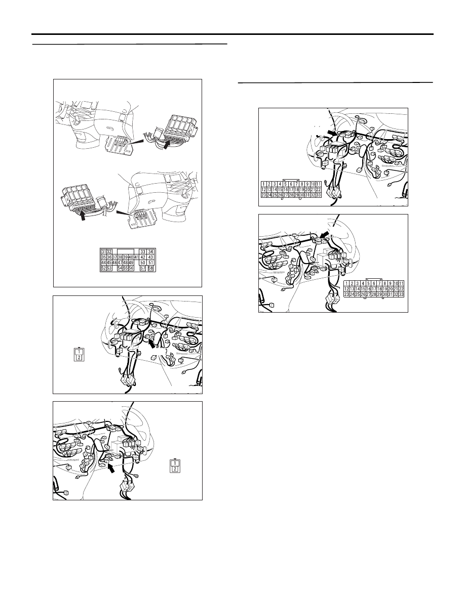
Connector: C-111
<L.H. drive vehicles>
<R.H. drive vehicles>
C-111 (GR)
C-111 (GR)
AC311913AG
C-131
Connector: C-131
<L.H. drive vehicles>
AC311916AG
C-131
Connector: C-131
<R.H. drive vehicles>
AC311913AE
C-32
Connector: C-32
<L.H. drive vehicles>
AC311916AE
C-01
Connector: C-01
<R.H. drive vehicles>