Mitsubishi Grandis. Manual - part 677


  Index      Mitsubishi     Mitsubishi Grandis - service repair manual


Search            


Content   ..  675  676  677  678   ..


Mitsubishi Grandis. Manual - part 677


DOOR

BODY

42-36

NOTE: When the power window sub switch of each 
seat is replaced, operate the power window main 
switch to fully close the applicable power window by 
one-shot up action (It is because the power window 
sub switch does not have one-shot up/down 
function).

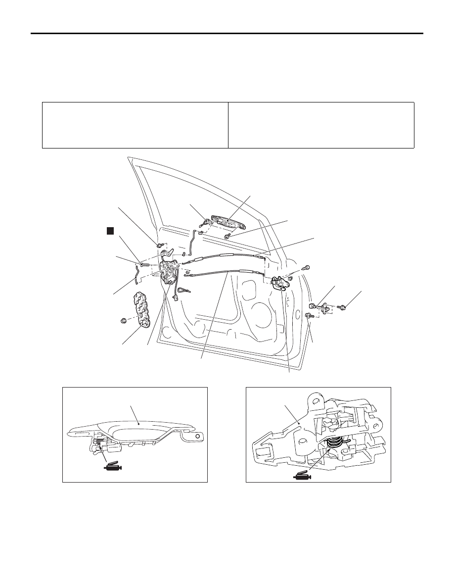
DOOR HANDLE AND LATCH

REMOVAL AND INSTALLATION

M1423004600470

Pre-removal Operation
• Door Trim Assembly Removal (Refer to GROUP 52A, 

Door Trim 

P.52A-12

).

Post-installation Operation
• Door Inside Handle Play Check (Refer to 

P.42-29

).

• Door Outside Handle Play Check (Refer to 

P.42-29

).

• Door Trim Assembly Installation (Refer to GROUP 52A, 

Door Trim 

P.52A-12

).

AC303146

AC310940

AC302891

AC208142

1

1

2

3

4

5

6

7

8

8

9

10

AB

<Front door>

5.0 ± 1.0 N·m

5.0 ± 1.0 N·m

5.0 ± 1.0 N·m

5.0 ± 1.0 N·m

24 ± 4 N·m

N

Door handle and door latch 
removal steps

>>B<<

1.

Door inside handle

Rear lower sash (Refer to 

P.42-33

).

2.

Screw

3.

Door latch assembly

4.

Inside lock cable

5.

Inside handle cable

6.

Outside handle rod

7.

Key cylinder

8.

Door outside handle

Door handle and door latch 
removal steps (Continued)

DOOR

BODY

42-37

Door check removal steps

Waterproof film (Refer to 

P.42-40

).

Front lower sash (Refer to 

P.42-33

).

>>A<<

9.

Door check
Door panel core removal steps

Power window regulator (Refer to 

P.42-33

).

10. Door panel core

AC303147

AC310941

AC302891

AC208142

1

1

2

2

3

4

5

6

7

8

AB

<Rear door>

5.0 ± 1.0 N·m

5.0 ± 1.0 N·m

5.0 ± 1.0 N·m

24 ± 4 N·m

N

Door handle and door check 
removal steps

>>B<<

1.

Door inside handle

Waterproof film (Refer to 

P.42-40

).

2.

Door outside handle

Rear lower sash (Refer to 

P.42-33

).

3.

Screw

4.

Door latch assembly

5.

Inside lock cable

6.

Inside handle cable

7.

Outside handle rod
Door check removal steps

Waterproof film (Refer to 

P.42-40

).

>>A<<

8.

Door check

Door handle and door check 
removal steps (Continued)

DOOR

BODY

42-38

INSTALLATION SERVICE POINTS
>>A<< DOOR CHECK INSTALLATION

Install the door check with the following identification 
marks facing upward.

>>B<< DOOR INSIDE HANDLE 
INSTALLATION

When connecting the inside cable to the door inside 
handle, ensure that the door latch and the inside 
handle are unlocked.

INSPECTION

M1423004700563

FRONT DOOR LOCK ACTUATOR CHECK

ACTUATOR OPERATION CHECK

Item

Identification 
mark

Front Door

Left side

55L

Right side

55R

Rear Door

Left side

56L

Right side

56R

AC302892 AB

A

Identification mark

View A

Lever 
position

Battery connection Lever 

operation

At the 
"LOCK" 
position

• Connect terminal 

No.4 and the 
negative battery 
terminal.

• Connect terminal 

No.6 and the 
positive battery 
terminal.

The lever 
moves from the 
"LOCK" 
position to the 
"UNLOCK" 
position.

At the 
"UNLOCK" 
position

• Connect terminal 

No.6 and the 
negative battery 
terminal.

• Connect terminal 

No.4 and the 
positive battery 
terminal.

The lever 
moves from the 
"UNLOCK" 
position to the 
"LOCK" 
position.

4

2
5

3
6

1

4

2
5

3
6

1

AC208145

B

A

AB

Lever

UNLOCK

<Front left side>

<Front right side>

LOCK

View A

Lever

UNLOCK

LOCK

View B

DOOR

BODY

42-39

ACTUATOR SWITCH CHECK <DRIVER’S SIDE 
(LH DRIVE VEHICLES)>

ACTUATOR SWITCH CHECK <DRIVER’S SIDE 
(RH DRIVE VEHICLES)>

REAR DOOR LOCK ACTUATOR CHECK

ACTUATOR OPERATION CHECK

DOOR LOCK KEY CYLINDER SWITCH 
CHECK <PASSENGER’S SIDE>

<LH DRIVER VEHICLES>

Lever position Tester 

connection

Specified 
condition

At the "LOCK" 
position

− 2

Less than 2 
ohms

At the 
"UNLOCK" 
position

− 3

Less than 2 
ohms

Lever position Tester 

connection

Specified 
condition

At the "LOCK" 
position

− 3

Less than 2 
ohms

At the 
"UNLOCK" 
position

− 3

Less than 2 
ohms

4

2
5

3
6

1

AC208587

4

2
5

3
6

1

B

A

AB

Lever

UNLOCK

LOCK

Lever

UNLOCK

LOCK

<Rear left side>

<Rear right side>

View A

View B

Lever 
position

Battery connection

Lever 
operation

At the 
"LOCK" 
position

• Connect terminal 

No.4 and the 
negative battery  
terminal.

• Connect terminal 

No.6 and the 
positive battery  
terminal.

The lever 
moves from 
the "LOCK" 
position to the 
"UNLOCK" 
position.

At the 
"UNLOCK" 
position

• Connect terminal 

No.6 and the 
negative battery  
terminal.

• Connect terminal 

No.4 and the 
positive battery  
terminal.

The lever 
moves from 
the "UNLOCK" 
position to the 
"LOCK" 
position.

Switch 
position

Tester 
connection

Specified 
condition

LOCK

− 3

Less than 2 
ohms

UNLOCK

− 3

Less than 2 
ohms

AC310942

AC303028

A

AB

View A

LOCK

UNLOCK


Content   ..  675  676  677  678   ..