Mitsubishi Grandis. Manual - part 644
ON-VEHICLE SERVICE
ENGINE LUBRICATION
12-5
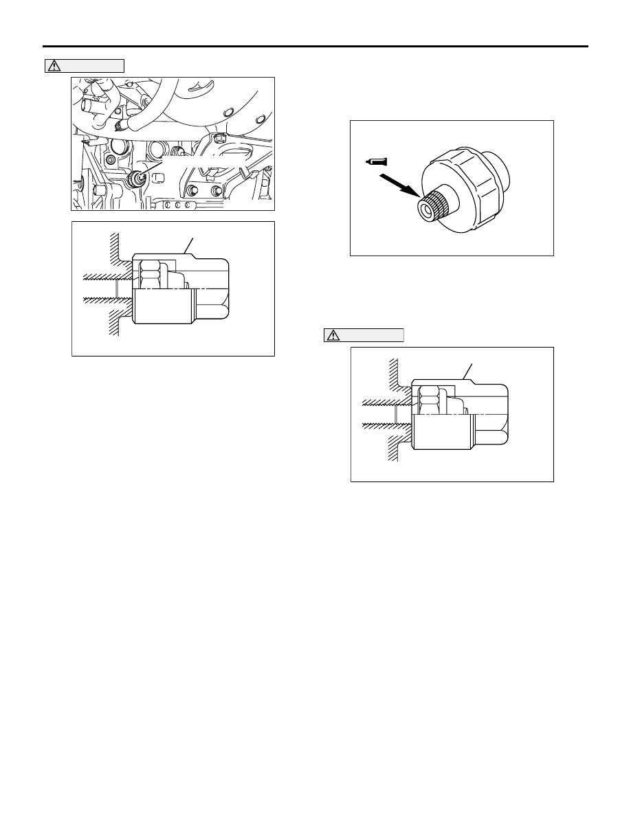
CAUTION
Since sealant is applied to the thread of oil
pressure switch, take care not to damage the oil
pressure switch when removing it.
2. Use the special tool Oil pressure switch wrench
(MD998054) to remove the oil pressure switch.
NOTE: Remove the terminal of oil pressure switch
where the special tool Oil pressure switch wrench
(MD998054) is not fitted.
3. Install the oil pressure gauge.
NOTE: Use an adapter of PT 1/8 thread.
4. Run the engine to warm it.
5. After the engine has been warmed up, check that
oil pressure is within the standard value.
Standard value:
At idle: 29 kPa or more
At 3,500 r/min: 294
− 686 kPa
6. Remove the oil pressure gauge.
7. Apply the specified sealant to the thread of oil
pressure switch.
Specified sealant: 3M ATD Part No. 8660 or
equivalent
CAUTION
Do not start the engine within one hour after the
oil pressure switch has been installed.
8. Use the special tool Oil pressure switch wrench
(MD998054) to tighten the oil pressure switch to
the specified torque.
Tightening torque: 19
± 3 N⋅m
AK300026AC
Oil pressure switch
AKX00294
MD998054
AD
AKX00295AD
AKX00294
MD998054
AD