Mitsubishi Grandis. Manual - part 645
CHARGING SYSTEM
ENGINE ELECTRICAL
16-4
SPECIAL TOOLS
M1161000600367
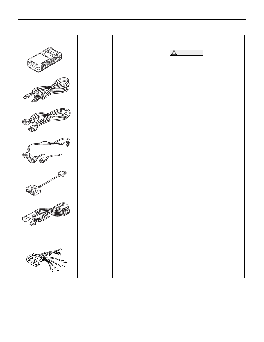
Tool
Number
Name
Use
MB991955
A: MB991824
B: MB991827
C: MB991910
D: MB991911
E: MB991825
F: MB991826
MUT-III sub assembly
A: Vehicle
communication
interface (V.C.I.)
B: MUT-III USB cable
C: MUT-III main harness
A (Vehicles with CAN
communication
system)
D: MUT-III main harness
B (Vehicles without
CAN communication
system)
E: MUT-III measurement
adapter
F: MUT-III trigger
harness
Checking the idle speed
CAUTION
For vehicles with CAN
communication, use MUT-III
main harness A to send
simulated vehicle speed. If you
connect MUT-III main harness B
instead, the CAN
communication does not
function correctly.
MB991519
Alternator test harness
Checking the alternator
("S" terminal voltage)
MB991910
MB991826
MB991955
MB991911
MB991824
MB991827
MB991825
A
B
C
D
E
F
DO NOT USED