Mitsubishi Grandis. Manual - part 642
ENGINE ASSEMBLY
ENGINE MECHANICAL
11A-45
REMOVAL SERVICE POINTS
<<A>> DRIVE BELT REMOVAL
The following operations will be needed due to the
introduction of the serpentine drive system with the
drive belt auto-tensioner.
1. Securely insert the spindle handle or ratchet
handle with a 12.7 mm insertion angle into the jig
hole of the auto-tensioner.
2. Rotate the auto-tensioner anti-clockwise and align
hole A with hole B.
AC312969AB
AC312969
18
17
16
15
14
13
12
11
10
9
N
8
78 ± 7 N·m
78 ± 7 N·m
78 ± 7 N·m
(Engine oil)
5.0 ± 1.0 N·m
24 ± 4 N·m
44 ± 10 N·m
78 ± 7 N·m
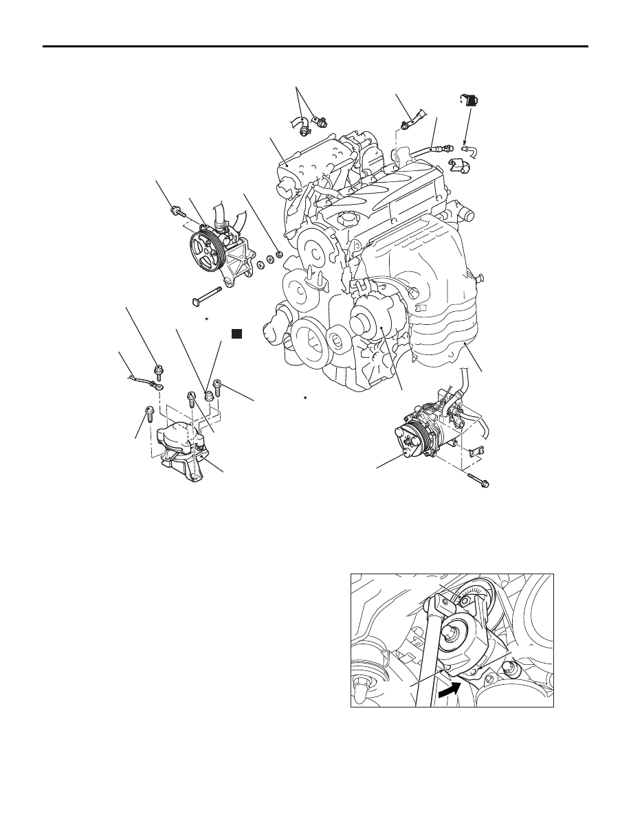
Removal steps
<<B>>
8.
Power steering oil pump and
bracket assembly
<<C>>
9.
A/C compressor and clutch
assembly
10. Exhaust manifold (Refer to GROUP
15, Exhaust Manifold
11. Alternator assembly (Refer to
GROUP 16, Charging System,
Alternator Assembly
12. Heater water hoses connection
13. Fuel return line hose connection
<<D>>
>>E<<
14. Fuel high-pressure hose
connection
<<E>>
>>D<<
•
Transmission assembly
>>C<<
•
Radiator assembly
15. Earth cable connection
16. Self-locking nuts
<<G>>
>>B<<
17. Engine front mounting bracket
<<H>>
>>A<<
18. Engine assembly
AC301703
AC301704AB
Hole A
Auto-tensioner
Hole B