Mitsubishi Grandis. Manual - part 641
TIMING BELT
ENGINE MECHANICAL
11A-41
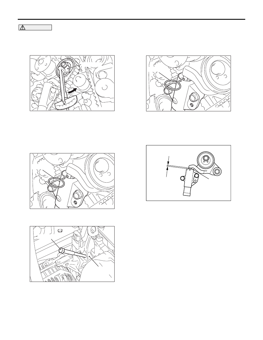
CAUTION
When tightening the mounting bolt, ensure that
the timing belt tensioner pulley does not rotate
with the bolt. Allowing it to rotate with the bolt
can cause deficient tension of the belt.
6. With special tool tensioner wrench (MD998767)
and torque wrench, apply tension torque 3.5 N
⋅m
to the valve timing belt, and tighten the timing belt
tensioner pulley mounting bolt to the specified
torque.
Tightening torque: 48
± 5 N⋅m
7. Remove wire or pin inserted to timing belt
tensioner adjuster.
8. Remove special tool adjusting bolt (MD998738),
and install the rubber plug to the timing belt under
cover.
9. Rotate crankshaft clockwise two turns, and leave
it for about 15 minutes.
10.Insert wire or pin removed in Step 7 again, and
ensure that it can be pulled out with a light load.
When wire or pin can be lightly removed,
appropriate tension is applied on timing belt. In
this case, remove wire or pin.
Also the projection of timing belt tensioner
adjuster rod (A) is within the standard value,
appropriate tension is applied.
Standard value (A): 3.8
− 4.5 mm
11.If wire or pin cannot be easily pulled out, repeat
Step 1 through Step 9 to reach proper valve timing
belt tension.
AC301859
MD998767
AB
AC301857AB
Wire or pin
AC301452AB
MD998738
Timing belt
under cover
AC301857AB
Wire or pin
AC301375
AB
A
Rod