Mitsubishi Grandis. Manual - part 639


  Index      Mitsubishi     Mitsubishi Grandis - service repair manual


Search            


Content   ..  637  638  639  640   ..


Mitsubishi Grandis. Manual - part 639


TIMING BELT

ENGINE MECHANICAL

11A-33

TIMING BELT

REMOVAL AND INSTALLATION

M1112004300913

Pre-removal Operation
• Engine room side cover (RH) Removal.
• Crankshaft Shaft Damper Pulley Removal (Refer to 

P.11A-15

).

Post-installation Operation
• Crankshaft Shaft Damper Pulley Installation (Refer to 

P.11A-15

).

• Drive Belt Tension Check (Refer to 

P.11A-7

).

• Engine room side cover (RH) Installation.
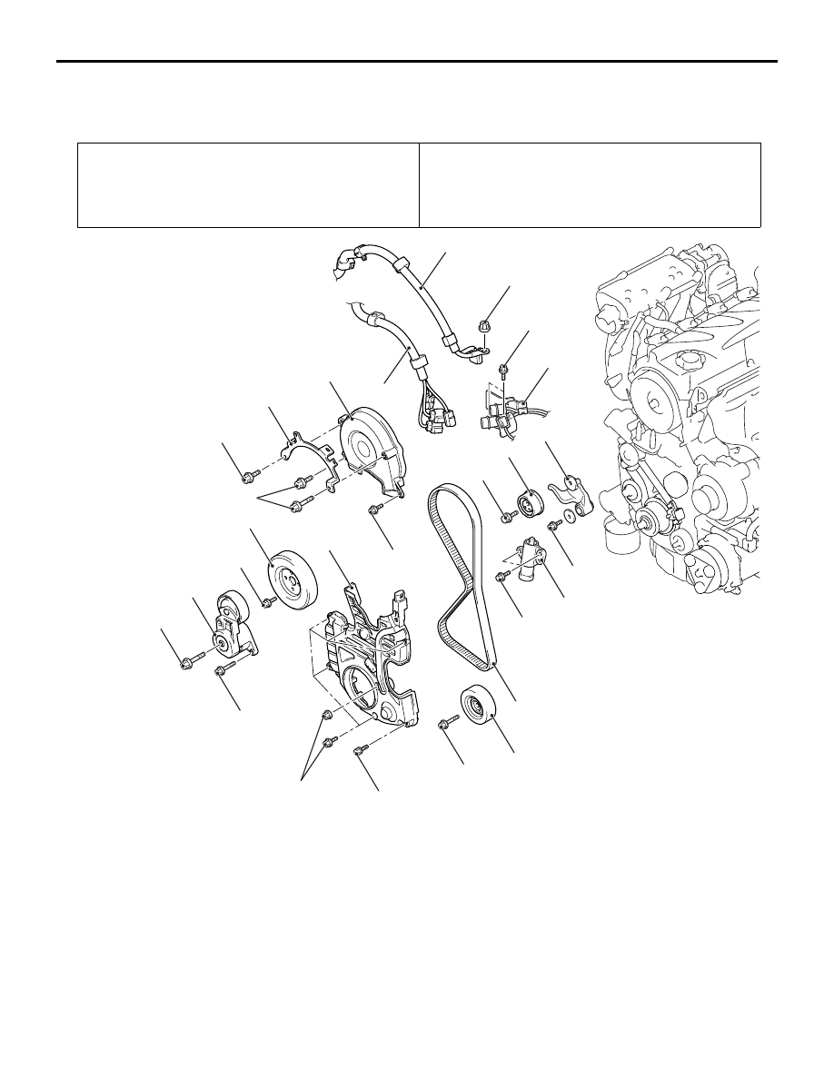
AC302084AB

14 ± 1 N·m

1

13

12

10

9

8

7

6

5

11

4

3

2

14 ± 1 N·m

8.8 ± 1.0 N·m

44 ± 10 N·m

22 ± 4 N·m

11 ± 1 N·m

9.0 ± 1.0 N·m

11 ± 1 N·m

79 ± 5 N·m

11 ± 1 N·m

21 ± 4 N·m

48 ± 5 N·m

23 ± 3 N·m

14 ± 3 N·m

Removal steps

1.

Control wiring harness connection 

2.

Battery wiring harness connection 

3.

Connector bracket

4.

Harness bracket

5.

Timing belt upper cover

6.

Water pump pulley

7.

Idler pulley

8.

Auto-tensioner

9.

Timing belt lower cover 

<<A>>

Brake fluid reservoir assembly

Engine front mounting bracket 
(Refer to GROUP 32, Engine 
Mount 

P.32-3

).

>>G<<

Valve timing belt tension 
adjustment (Installation only)

<<B>>

>>F<<

10. Valve timing belt 

>>E<<

11. Timing belt tensioner pulley
12. Timing belt tensioner arm

>>D<<

13. Timing belt tensioner adjuster

Removal steps (Continued)

TIMING BELT

ENGINE MECHANICAL

11A-34

REMOVAL SERVICE POINTS
<<A>> BRAKE FLUID RESERVOIR 
ASSEMBLY REMOVAL

With the hose installed, remove the brake fluid 
reservoir assembly from the vehicle. (Refer to 
GROUP 35A, MASTER CYLINDER ASSEMBLY 
AND BRAKE BOOSTER 

P.35A-14

).

NOTE: Tie the removed brake fluid reservoir 
assembly with a string at a position where it will not 
interfere with the removal and installation of timing 
belt.

AC312966 AB

AC312966

19

18

17

16

15

14

22

20

21

(Engine oil)

35 ± 6 N·m

8.5 ± 0.5 N·m

19 ± 3 N·m

167 N·m

Removal steps

14. Timing belt Idler pulley
15. Timing belt lower cover bracket
16. Crank angle sensor

<<C>>

>>C<<

17. Crankshaft pulley centre bolt

<<C>>

>>C<<

18. Crankshaft pulley washer

<<C>>

>>C<<

19. Crankshaft camshaft drive sprocket

>>C<<

20. Crankshaft angle sensing blade

>>B<<

Balancer timing belt tension 
adjustment (Installation only)

>>A<<

21. Balancer timing belt tensioner

<<D>>

>>A<<

22. Balancer timing belt 

TIMING BELT

ENGINE MECHANICAL

11A-35

<<B>> VALVE TIMING BELT REMOVAL

CAUTION

Never turn the crankshaft anti-clockwise.

1. Turn the crankshaft clockwise, align each timing 

mark to set No.1 cylinder to TDC of its 
compression stroke.

2. Remove the timing belt under cover rubber plug 

and then set special tool adjusting bolt 
(MD998738).

3. Screw in the special tool with hands until it 

contacts the timing belt tensioner arm.

CAUTION

The special tool can be gradually installed at a 
rate of a 30 degree turn per second. If it is 
screwed in all at once, the timing belt tensioner 
adjuster rod will not easily retract and the special 
tool may bend.

4. Gradually screw in the special tool and then align 

the timing belt tensioner adjuster rod set hole A 
with the timing belt tensioner adjuster cylinder set 
hole B.

5. Insert a wire or pin in the set hole aligned.

CAUTION

To reuse the valve timing belt, draw an arrow 
indicating the rotating direction (clockwise) on 
the back of the belt using chalk, etc.
6. After removal of the special tool, loosen the timing 

belt tensioner pulley mounting bolts and remove 
the valve timing belt.

AC301866

AB

Timing mark

Crankshaft
camshaft
drive sprocket

Camshaft
sprocket

Timing mark

Timing mark

Engine oil pump 
sprocket

AC301452AB

MD998738

Timing belt
under cover

AC301373

AB

MD998738

Timing belt
tensioner arm

AC301856

A

B

AB

AC302414AB

Timing belt tensioner 
pulley mounting bolt 

Wire or pin

TIMING BELT

ENGINE MECHANICAL

11A-36

<<C>> CRANKSHAFT PULLEY CENTRE 
BOLT/CRANKSHAFT PULLEY 
WASHER/CRANKSHAFT CAMSHAFT 
DRIVE SPROCKET REMOVAL

1. Use the following special tools to hold the 

crankshaft camshaft drive sprocket.

• Special spanner (MB991367)

• Pin (MB991385)

2. Loosen the crankshaft pulley centre bolt and 

remove the crankshaft pulley washer and 
crankshaft camshaft drive sprocket.

<<D>> BALANCER TIMING BELT 
REMOVAL

CAUTION

To reuse the balancer timing belt, draw an arrow 
indicating the rotating direction on the back of 
the belt using chalk, etc.

INSTALLATION SERVICE POINTS
>>A<< BALANCER TIMING 
BELT/BALANCER TIMING BELT 
TENSIONER INSTALLATION

1. Ensure that the crankshaft balancer shaft drive 

sprocket timing marks and balancer shaft 
sprocket timing marks are aligned.

2. Install the balancer timing belt on the crankshaft 

balancer shaft drive sprocket and balancer shaft 
sprocket. There should be no slack on the tension 
side.

3. Assemble and temporarily fix the centre of the 

pulley of the balancer timing belt tensioner so that 
it is at the top left from the centre of the 
assembling bolt, and the pulley flange is at the 
front-side of the engine.

4. Adjust the balancer timing belt tension.

AC102332AB

MB991385

MB991367

Crankshaft
camshaft
drive 
sprocket

AC301402AB

Balancershaft 
sprocket

Belt tension 
side

Timing 
mark

Crankshaft
balancershaft
drive sprocket

Timing 
mark

AC301403AB

Centre of
the pulley

Centre of the 
mounting bolt


Content   ..  637  638  639  640   ..