Mitsubishi Grandis. Manual - part 638


  Index      Mitsubishi     Mitsubishi Grandis - service repair manual


Search            


Content   ..  636  637  638  639   ..


Mitsubishi Grandis. Manual - part 638


CYLINDER HEAD GASKET

ENGINE MECHANICAL

11A-29

REMOVAL SERVICE POINTS
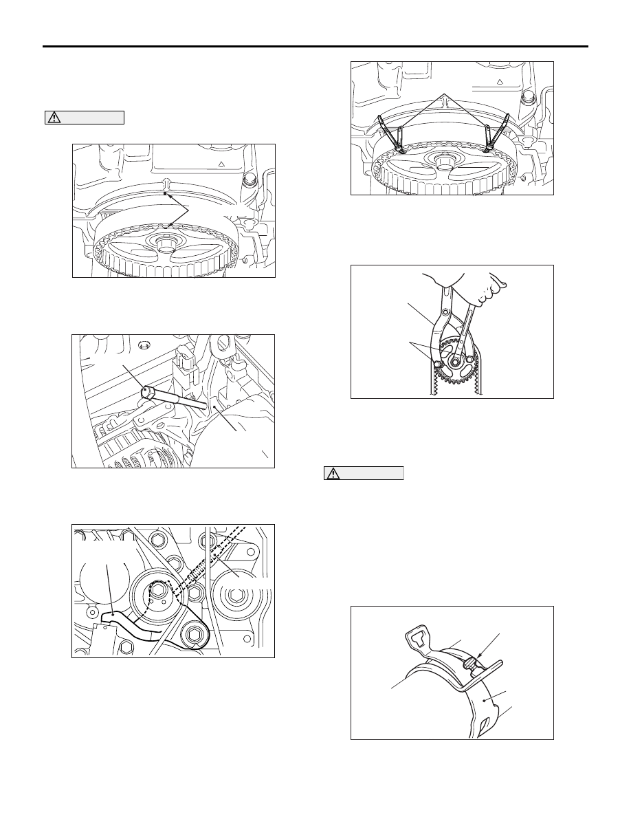
<<A>> CAMSHAFT SPROCKET 
REMOVAL

CAUTION

Never turn the crankshaft anti-clockwise.

1. Turn the crankshaft clockwise, align the timing 

marks on the camshaft sprocket to set No.1 
cylinder to TDC of its compression stroke.

2. Remove the timing belt under cover rubber plug 

and then set special tool adjusting bolt 
(MD998738).

3. Screw in the special tool until it comes in contact 

with the timing belt tensioner arm.

4. Secure the camshaft sprocket and valve timing 

belt with wiring bands and so on to prevent 
slippage between the camshaft sprocket and 
valve timing belt.

5. Use the following special tools to hold the 

camshaft sprocket.

• Front hub and flange yoke holder (MB990767)

• Pin (MD998719)

CAUTION

Do not rotate the crankshaft after camshaft 
sprocket removal.
6. Remove the camshaft sprocket with the valve 

timing belt and place it on the timing belt lower 
cover.

<<B>> RADIATOR UPPER HOSE/HOSE 
CLIP DISCONNECTION

Break off the tip of hose clip claw and spread out the 
hose clip, then disconnect the radiator upper hose.

NOTE: If there is a hose clip claw, the hose clip 

cannot spread to capacity.

AC301450AB

Timing mark

AC301452AB

MD998738

Timing belt
under cover

AC301373

AB

MD998738

Timing belt
tensioner arm

AC107621

AC301451AC

Wiring band

AC100302

MD998719

MB990767

AB

AC302615

Hose clip

Claw (Tip)

AE

CYLINDER HEAD GASKET

ENGINE MECHANICAL

11A-30

<<C>> FUEL HIGH-PRESSURE HOSE 
REMOVAL

1. Remove the fuel high-pressure hose stopper.

2. Remove the fuel high-pressure hose in the 

direction shown in the figure while the retainer is 
pulled up. 
NOTE: If the retainer is released, install it after 
removing the fuel high-pressure hose.

<<D>> CYLINDER HEAD BOLTS 
REMOVAL

Use special tool cylinder head bolt wrench 
(MB991654) to loosen the cylinder head bolts in two 
or three steps in the order of the numbers shown in 
the illustration. If the cylinder head bolts cannot be 
pulled out due to the washer being trapped in the 
valve spring, raise the bolt slightly, then remove it 
while holding it by using a magnet.

INSTALLATION SERVICE POINTS
>>A<< CYLINDER HEAD GASKET 
INSTALLATION

CAUTION

Do not allow any foreign materials get into the 
coolant passages, oil passages and cylinder.
1. Degrease the cylinder head gasket mounting 

surface.

AC301860AB

Stopper

AC301861AB

Retainer 

AC301454AB

MB991654

10

5

2

8

3

9

7

4

6

1

Engine front

AC302180AB

Identification
mark "381"

Exhaust side

CYLINDER HEAD GASKET

ENGINE MECHANICAL

11A-31

2. Assemble to the cylinder block so the cylinder 

head gasket identification mark of "381" is at the 
top surface and on the exhaust side.

>>B<< CYLINDER HEAD BOLTS 
INSTALLATION

1. Check that the nominal length of each cylinder 

head bolt meets the limit. If it exceeds the limit, 
replace the bolts with a new one.

Limit (A): 99.4 mm

2. Apply a small amount of engine oil to the thread of 

the bolts and to the washers.

3. Use special tool cylinder head bolt wrench 

(MB991654) to tighten the cylinder head bolts in 
the following procedures.
(1) Tighten the bolts to 78 

± 2 N⋅m in the order 

shown.

(2) Loosen the bolts fully in the reverse sequence 

to that shown.

(3) Tighten the bolts to 20 

± 2 N⋅m in the order 

shown.

(4) Apply a paint mark to the heads of the cylinder 

head bolts and cylinder head, then tighten 90 
degree angle as shown.

CAUTION

• The bolt is not tightening sufficiently if the 

tightening angle is less than a 90 degree 
angle.

• If the tightening angle exceeds the standard 

specification, remove the bolt and start over 
from step 1.

(5) Tighten in a 90 degree angle as shown in the 

instructions of the figure, then check to see 
that the paint mark on the head of the cylinder 
head bolts and the paint mark on the cylinder 
head is on a linear line.

AC102537

A

AC

(Engine oil)

AC301456AB

MB991654

10

9

7

5

2

4

8

6

1

3

Engine front

AC102331AB

Paint marking

90˚

90˚ 

Step (4)

Step (5)

Paint marking

CYLINDER HEAD GASKET

ENGINE MECHANICAL

11A-32

>>C<< FUEL HIGH-PRESSURE HOSE 
INSTALLATION

CAUTION

After connecting the fuel high-pressure hose, 
slightly pull it to ensure that it is installed 
securely. Also confirm that there is a play 
approximately 3 mm. Then install the stopper 
securely.
Apply a small amount of engine oil to the fuel line 
pipe and then install the fuel high-pressure hose.

>>D<< RADIATOR UPPER HOSE/HOSE 
CLIP CONNECTION

CAUTION

Never reuse the hose clip whose claw is broken 
off to prevent the rusting.
1. insert a new hose clip into the radiator upper 

hose.

2. Insert the radiator upper hose until the protrusion 

of water outlet fitting.

3. Remove the hose clip claw and shorten the hose 

clip, then secure the radiator upper hose.

>>E<< CAMSHAFT SPROCKET 
INSTALLATION

1. Use the following special tool as during removal to 

hold the camshaft sprocket.

• Front hub and flange yoke holder (MB990767)

• Pin (MD998719)

2. Tighten the camshaft sprocket mounting bolt to 

the specified torque.

Tightening torque: 89 

± 9 Nm

>>F<< Brake booster vacuum hose 
INSTALLATION

1. Insert the brake booster vacuum hose thoroughly 

until it contacts the inlet manifold so that its mating 
mark faces towards the direction shown.

2. Secure the brake booster vacuum hose with hose 

clip.

AC301864AB

3 mm

Fuel 
high-pressure 
hose

Fuel line pipe
(Engine oil applied)

AC301863AB

Stopper

AC100302

MD998719

MB990767

AB

AC311486

Mating mark

AB

AC311486


Content   ..  636  637  638  639   ..