Mitsubishi Grandis. Manual - part 354


  Index      Mitsubishi     Mitsubishi Grandis - service repair manual


Search            


Content   ..  352  353  354  355   ..


Mitsubishi Grandis. Manual - part 354


COMBINATION METER

CHASSIS ELECTRICAL

54A-35

TROUBLESHOOTING

TROUBLESHOOTING

M1543000701262

STANDARD FLOW OF DIAGNOSIS 
TROUBLESHOOTING

Refer to GROUP 00 

− How to Use 

Troubleshooting/Inspection Service Points 

P.00-5

.

DIAGNOSIS FUNCTION

M1543007000603

HOW TO READ DIAGNOSIS CODE

Refer to GROUP 00, How to Use 
Troubleshooting/Inspection Service Points 

P.00-5

HOW TO ERASE DIAGNOSIS CODE

Refer to GROUP 00, How to Use 
Troubleshooting/Inspection Service Points 

P.00-5

DIAGNOSIS CODE CHART

M1543007100592

CAUTION

During diagnosis, a diagnosis code associated 
with other system may be set when the ignition 
switch is turned on with connector(s) 
disconnected. On completion, confirm all 
systems for diagnosis code(s). If diagnosis 
code(s) are set, erase them all.

NOTE: 

*

: For M/T-vehicles, diagnosis code No. 12 

does not mean that there is a problem.
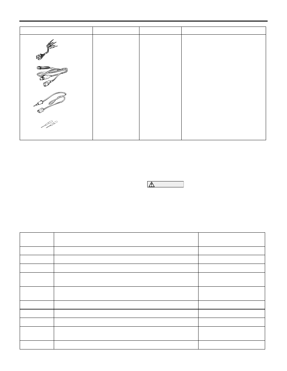
MB991223

A: MB991219
B: MB991220
C: MB991221
D: MB991222

Harness set

A: Test harness
B: LED harness
C: LED harness 

adapter

D: Probe

Making voltage and resistance 
measurements during 
troubleshooting

A: Connect pin contact pressure 

inspection

B: Power circuit inspection
C: Power circuit inspection
D: Commercial tester connection

Tool

Number

Name

Application

MB991223

A

B

C

D

AT

Diagnosis 
code No.

Diagnosis item

Reference page

B1200

Malfunction odometer

P.54A-36

B1201

Trouble of fuel information

P.54A-37

U1073

Bus Off

P.54A-43

U1100

Engine-ECU <M/T> or engine-A/T-ECU <A/T> time-out 
(related to engine)

P.54A-44

U1101

*

Engine-A/T-ECU <A/T> time-out (related to automatic 
transmission)

P.54A-46

U1102

ABS-ECU or TCL/ASC-ECU time-out

P.54A-47

U1109

ETACS-ECU time-out

P.54A-49

U1112

SRS-ECU time-out

P.54A-50

U1120

Failure information on engine-ECU <M/T> or engine-A/T-ECU 
<A/T> (related to engine)

P.54A-51

U1206

Flag invalid

P.54A-52

COMBINATION METER

CHASSIS ELECTRICAL

54A-36

DIAGNOSTIC TROUBLE CODE 
PROCEDURES

Code No.B1200 Malfunction odometer

TROUBLE JUDGMENT

This code is stored when the odometer value cannot 
be determined when reading, writing or verifying the 
EEPROM storing the odometer value, or the 
odometer displays abnormal value.  

COMMENTS ON TROUBLE SYMPTOM

The combination meter may be defective.

POSSIBLE CAUSES

Malfunction of the combination meter

DIAGNOSTIC PROCEDURE

Check whether the diagnosis code is reset.

Recheck if the diagnosis code is set.
(1) Erase the diagnosis code.
(2) Turn the ignition switch to "ON" position.
(3) Check if the diagnosis code is set.

Q: Is the check result satisfactory?

YES : 

Replace combination meter.

NO : 

An intermittent malfunction is suspected. 
Refer to GROUP 00, How to Use 
Troubleshooting/Inspection Service Points 

− 

How to Cope with Intermittent Malfunctions 

P.00-5

.

COMBINATION METER

CHASSIS ELECTRICAL

54A-37

 Code No.B1201 Trouble of fuel information

COMMENTS ON TROUBLE SYMPTOM

If only the fuel gauge does not operate, the fuel tank 
pump and gauge unit assembly, fuel tank gauge unit, 
combination meter, wiring harness or connector(s) 
may be defective.

POSSIBLE CAUSES

• Damaged harness wires and connectors

• Malfunction of fuel tank gauge unit

• Malfunction of fuel tank pump and gauge unit 

assembly

• Malfunction of combination meter

Wire colour code
B : Black     LG : Light green     G : Green     L : Blue     W : White     Y : Yellow     SB : Sky blue
BR : Brown     O : Orange     GR : Gray     R : Red     P : Pink     V : Violet

Fuel Gauge Circuit

COMBINATION
METER

CPU

FUEL TANK
GAUGE
UNIT

FUEL TANK
PUMP AND
GAUGE UNIT
ASSEMBLY

F/GA

COMBINATION METER

CHASSIS ELECTRICAL

54A-38

DIAGNOSIS PROCEDURE

Step 1. Connector check: Fuel tank pump and 
gauge unit assembly connector D-15.

Q: Is fuel tank pump and gauge unit assembly 

connector C-02 in good condition?

YES : 

Go to Step 2.

NO : 

Repair the connector, and then go to Step 
11.

Step 2. Check the fuel gauge circuit.

(1) Disconnect fuel tank pump and gauge unit 

assembly connector D-15.

(2) Use special tool MB991219 to connect a test 

lamp (12 V - 3.4 W) between the wiring harness 

connector terminals 1 and 2.

(3) Turn the Ignition switch to "ON" position.
(4) Check if the test lamp illuminates.

OK: Illuminates

Q: Is the check result satisfactory?

YES : 

Go to Step 8.

NO : 

Go to Step 3.

Step 3. Resistance measurement at fuel tank 
pump and gauge unit assembly connector D-15 
to check the earth circuit to the fuel tank pump 
and gauge unit assembly.

(1) Disconnect fuel tank pump and gauge unit 

assembly connector D-15, and measure at the 
wiring harness side.

(2) Turn the Ignition switch to "LOCK" (OFF) 

position.

(3) Disconnect the negative battery terminal.

(4) Measure the resistance value between terminal 1 

and earth.

OK: 2 ohms or less

Q: Is the check result normal?

YES : 

Go to Step 5.

NO : 

Go to Step 4.

AC310207

AG

Connector: D-15

D-15 (GR)

Harness side

AC310207

AG

Connector: D-15

D-15 (GR)

Harness side

AC302533

MB991219

AB

Test lamp
(12 V - 3.4 W)

AC310207

AG

Connector: D-15

D-15 (GR)

Harness side

AC310506

Connector D-15 
(Harness side)

CM


Content   ..  352  353  354  355   ..