Mitsubishi Grandis. Manual - part 352


  Index      Mitsubishi     Mitsubishi Grandis - service repair manual


Search            


Content   ..  350  351  352  353   ..


Mitsubishi Grandis. Manual - part 352


IGNITION SWITCH

CHASSIS ELECTRICAL

54A-27

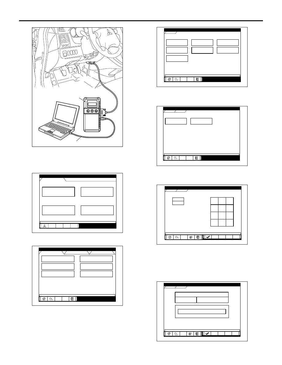
1. Connect the MUT-III to the diagnosis connector 

(16-pin).

2. Turn the ignition switch to "ON" position.

3. Select "System select" from the start-up screen.

4. Choose "IMMOBILIZER" from the "POWER 

TRAIN" tab.

5. Choose "Special Function" from "IMMOBILIZER" 

screen.

6. Choose "Key registration" from "Special Function" 

screen.

7. Enter the vehicle’s password (secret code) on the 

"Key registration" screen, and then click the check 
mark icon. Follow the prompts on the screen to 
insert key(s) into the ignition switch to begin key 
registration.

AC302297

AC310120

AB

MB991827

16-pin

MB991910

MB991824

System select

Special function

CAN bus diagnosis

Function Select Menu

Menu

AC209666

Maintenance

AD

MPI/GDI/DIESEL

ELC-A/T/CVT

IMMOBILIZER

SS4II

TCL/STARLTY CONTROL

AUTO CRUISE

CHASSIS

BODY

System Select Menu

POWER TRAIN

AC305175

Check Chart For

 Problem Sy

Data List

Special 

Function

Self-diagnosis

Simulated Vehicle 

Speed Out

Resistor

Voltmeter

POWERTRAIN

IMMOBILIZER

IMMOBILIZER

AC305176

Key ID registration

Additional Key

Registration

POWERTRAIN

Special Function

IMMOBILIZER

Special Function

AC305177

POWERTRAIN

IMMOBILIZER

Special Function

7

8

9

4

5

6

1

2

3

0

Back

Back

Space

Space

Clear

Clear

Key registration

AC207300

AD

POWERTRAIN

IMMOBILIZER

Special Function

IMMOBILIZER-ECU registration

Progress

In-Complete

Key registration

AC207302

IGNITION SWITCH

CHASSIS ELECTRICAL

54A-28

8. If the key ID was registered successfully, 

"Progress" indication will turn active (gray). Then 
the registration process completes. If the key ID 
failed to be registered, "In-Complete" indication 
will turn active (gray).

9. The number of keys currently registered will be 

displayed. To register an additional key, replace 
the ignition key with the next key to be registered 
within five seconds. Key ID registration screen will 
be displayed, then register another key.
NOTE: A maximum of eight different keys can be 
registered.

10.This completes the registration operation. Turn 

the ignition switch "LOCK" (OFF) and leave it off 
for approximately ten seconds.

11.Check that the engine can be started with each of 

the ignition keys.

12.Check that the immobilizer system diagnosis 

code and MPI system diagnosis code did not set.

13.If not diagnosis code is shown, terminate the 

MUT-III.

14.Turn the ignition switch to "LOCK" (OFF) position.
15.Disconnect MUT-III.

REGISTRATION OF ADDITIONAL KEYS 
WITH THE MUT-III

Additional key(s) can be registered with the MUT-III 
while keeping all existing key data.

CAUTION

To prevent damage to MUT-III, always turn the 
ignition switch to "LOCK" (OFF) position before 
connecting or disconnecting MUT-III.
NOTE: To register additional keys with the MUT-III, 
no registered keys must be lost.

1. Connect MUT-III to the 16-pin diagnosis 

connector.

2. Turn the ignition switch to "ON" position.
NOTE: Before registration, check that no diagnosis 
code is set. If a diagnosis code is set, resolve the 
problem beforehand.
3. Carry out steps 3 to 6 of the sub-section 

"Registration with MUT-III."

4. Choose "Transponder ID addition" from "Special 

Function" screen.

AC302297

AC310120

AB

MB991827

16-pin

MB991910

MB991824

Key ID registration

Additional Key

Registration

POWERTRAIN

Special Function

IMMOBILIZER

Special Function

AC305177

POWERTRAIN

IMMOBILIZER

Password

Special Function

7

8

9

4

5

6

1

2

3

0

Back

Back

Space

Space

Clear

Clear

Trasponder ID addition

AC207301

IGNITION SWITCH

CHASSIS ELECTRICAL

54A-29

5. Enter the vehicles password (secret code) on the 

"Transponder ID addition" screen, and then click 
the check mark icon.

6. If an additional registration is made successfully, 

the screen will ask if another key is registered or 
not. If the third ignition key is registered, remove 
the key, which has been registered. Then insert 
the third key within five seconds, and then turn it 
to the ON position.

7. Register the additional ignition key according to 

step 6 above. The number of the registered 
ignition keys are shown on "The number of 
registered key" screen.
NOTE: A maximum of eight different keys can be 
registered.

8. This completes the registration operation. Turn 

the ignition switch "LOCK" (OFF) and leave it off 
for approximately ten seconds.

9. Check that the engine can be started with each of 

the ignition keys.

10.Check that the immobilizer system diagnosis 

code and MPI system diagnosis code did not set.

11.If not diagnosis code is shown, terminate the 

MUT-III.

12.Turn the ignition switch to "LOCK" (OFF) position.
13.Disconnect MUT-III.

AC207301

AC209775

POWERTRAIN

IMMOBILIZER

Key ID register

The number of registered key

The number of registered key

3

Progre

Special Function

Trasponder ID addition

About Additional Transponder
ID SET

If register another key ID, press the

If register another key ID, press the
OK button after inserting a new key

OK button after inserting a new key
within 5 sec and turning on IG-SW

within 5 sec and turning on IG-SW.

IGNITION SWITCH

CHASSIS ELECTRICAL

54A-30

IGNITION SWITCH

REMOVAL AND INSTALLATION

M1543002100575

WARNING

Before removal of the air bag module, refer to GROUP 52B, Service Precautions (

P.52B-7

and Driver’s, Front Passenger’s Air Bag Module(s) and Clock Spring (

P.52B-225

).

When removing and installing the steering wheel, do not let it bump against the air bag 
module.

AC311940

1

1

2

3

4

5

6

7

AB

2.5 ± 0.5 N·m

Removal steps

Gearshift lever knob <M/T> (Refer 
to GROUP 22A, Transmission 
Control 

P.22A-7

).

Selector lever knob <A/T> (Refer to 
GROUP 23A, Transmission Control 

P.23A-144

).

Selector lever panel (Refer to 
GROUP 52A, Instrument Panel 
Assembly 

P.52A-2

).

Front scuff plate inner, Cowl side 
trim (Refer to GROUP 52A, Interior 
Trim 

P.52A-10

).

Fuel filler lid lock release handle 
(Refer to GROUP 42, Fuel Filler Lid 

P.42-7

).

Lower panel (Refer to GROUP 52A, 
Instrument Panel Assembly 

P.52A-2

).

1.

Steering column cover (Refer to 
GROUP 52A, Instrument Panel 
Assembly 

P.52A-2

).

2.

Steering wheel (Refer to GROUP 
37A, Steering Wheel 

P.37-14

).

3.

Clock spring and column switch 
assembly (Refer to GROUP 37A, 
Steering Shaft 

P.37-16

 an

GROUP 52B, Driver’s, Front 
Passenger’s Air Bag Module(s) and 
Clock Spring 

P.52B-225

).

4.

Ignition Switch

5.

Key reminder switch

6.

Immobilizer-ECU and key ring 
antenna assembly

<<A>>

7.

Steering lock cylinder

Removal steps (Continued)


Content   ..  350  351  352  353   ..