Mitsubishi Grandis. Manual - part 351


  Index      Mitsubishi     Mitsubishi Grandis - service repair manual


Search            


Content   ..  349  350  351  352   ..


Mitsubishi Grandis. Manual - part 351


IGNITION SWITCH

CHASSIS ELECTRICAL

54A-23

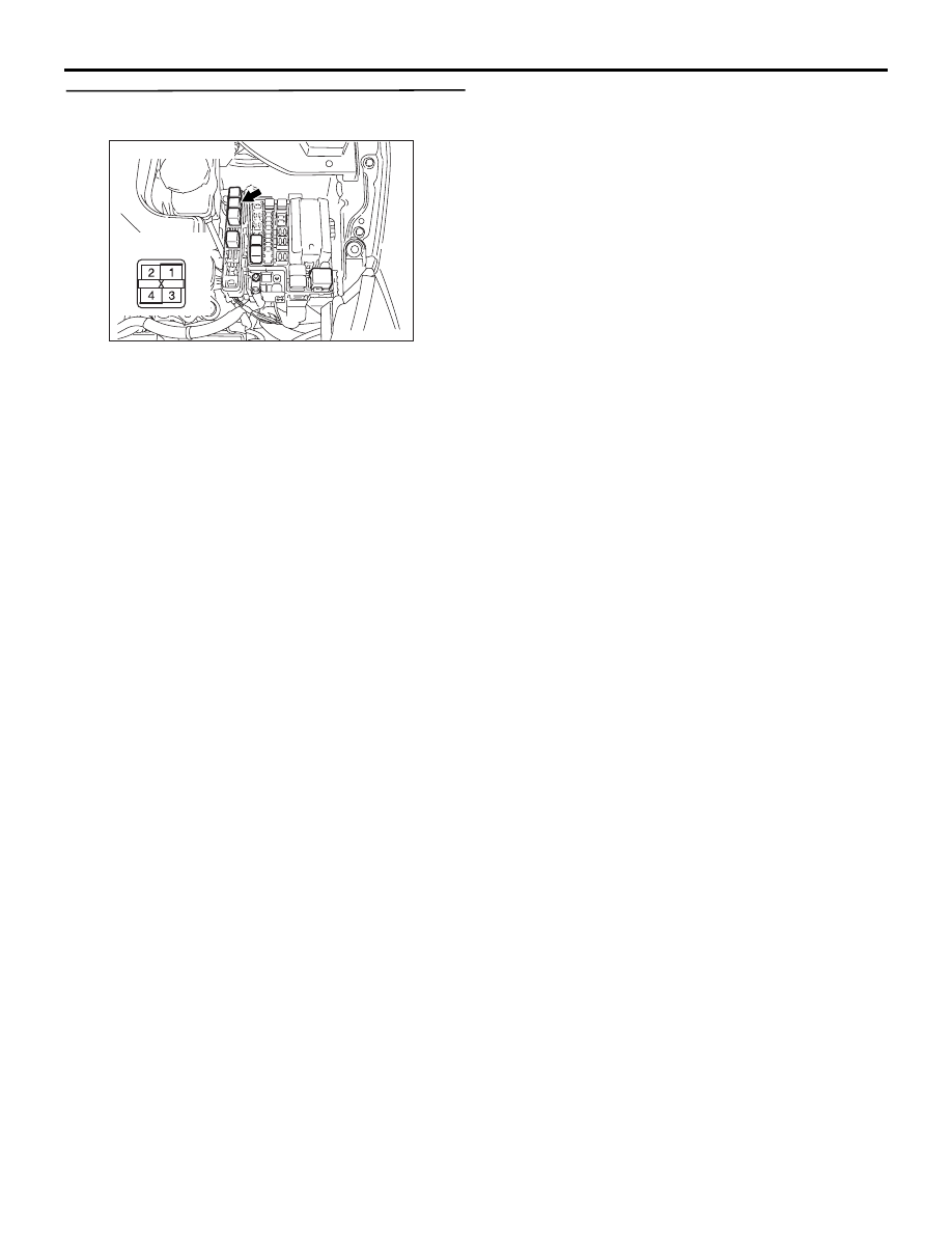
Step 3. Connector check: Engine control relay 
connector B-15X

Q: Is the check result normal?

YES : 

Go to Step 4.

NO : 

Repair the defective connector.

AC312585AB

Connector: B-15X

Relay box side

IGNITION SWITCH

CHASSIS ELECTRICAL

54A-24

Step 4. Check the wiring harness between engine 
control relay connector B-15X (terminal 1) and 
key reminder switch connector C-308 (terminal 
5).

NOTE: 

Prior to the wiring harness inspection, check joint 
connector C-116, intermediate connector C-18, and 
repair if necessary.

• Check the power supply line for open circuit.

Q: Are the wiring harness between engine control 

relay connector B-15X (terminal 1) and key 
reminder switch connector C-308 (terminal 5) in 
good condition?

YES : 

 Go to Step 5.

NO : 

Repair the wiring harness.

AC312585AB

Connector: B-15X

Relay box side

AC310153AE

Connector: C-308 <LHD>

Harness side

AC310183

AE

Connector: C-308 <RHD>

Harness side

AC310616

AG

Harness side

Connectors: C-18, C-116 <LHD>

C-116

C-116

C-18

C-18

AC310629AE

Harness side

Connectors: C-18, C-116 <RHD>

C-116

C-116

C-18

C-18

IGNITION SWITCH

CHASSIS ELECTRICAL

54A-25

Step 5. Resistance measurement at key reminder 
switch connector C-308 to check the earth circuit 
to the key reminder switch connector.

(1) Disconnect the key reminder switch connector 

C-308 and measure the resistance at key 
reminder switch connector C-308 harness side.

(2) Measure the resistance between terminal 3 and 

earth.

OK: 2 ohms or less

Q: Is the check result normal?

YES : 

The procedure is complete.

NO : 

Go to Step 6.

Step 6. Check the wiring harness between key 
reminder switch connector C-308 (terminal 3) and 
earth.

NOTE: 

Prior to the wiring harness inspection, check joint 
connector C-01 <RH drive vehicles>, and repair if 
necessary.

• Check the earth wires for open circuit.

Q: Are the wiring harness between key reminder 

switch connector C-308 (terminal 3) and earth in 
good condition?

YES : 

The procedure is complete.

NO : 

Repair the wiring harness.

DATA LIST REFERENCE TABLE

M1543007300411

AC310153AE

Connector: C-308 <LHD>

Harness side

AC310183

AE

Connector: C-308 <RHD>

Harness side

AC310506

Connector C-308 
(Harness side)

CC

AC310153AE

Connector: C-308 <LHD>

Harness side

AC310183

AE

Connector: C-308 <RHD>

Harness side

AC310631AE

Connector: C-01 <RHD>

Item No.

Inspection item

Inspection 
requirement

Normal condition

01

Key has been registered

Number of registered ignition keys

IGNITION SWITCH

CHASSIS ELECTRICAL

54A-26

CHECK IMMOBILIZER-ECU

M1543007600605

TERMINAL VOLTAGE CHECK TABLE

ON-VEHICLE SERVICE

HOW TO REGISTER ENCRYPTED CODE

M1543008100562

CAUTION

Because registering the encrypted codes is done 
after all previously-registered codes have been 
erased, you should keep all of the ignition keys 
that have already been registered accessible.
If the ignition key, immobilizer-ECU, engine-ECU 
<M/T> or engine-A/T-ECU <A/T> is replaced or an 
ignition key is added, encrypted codes of all the 
ignition keys must be registered. (A maximum of 
eight different ignition key can be registered). 
Moreover, when the immobilizer-ECU has been 
replaced, you will need to use MUT-III to register the 
immobilizer-ECU and input the vehicle secret code 
and to register the password (secret code) that the 
owner specifies into the immobilizer-ECU. If an 
attempt is made to start the engine with an 
unregistered ignition key, cranking occurs, but fuel 
supply is cut off to disable the engine. In 
approximately.
NOTE: Engine-ECU <M/T> or engine-A/T-ECU 
<A/T> has an encrypted code for immobilizer-ECU, 
and the encrypted code is registered in the 
immobilizer-ECU and ignition key.

POINTS TO NOTE DURING OPERATION

If none of the functions can be used, check the 
diagnosis codes, and after carrying out any 
necessary repairs, repeat the operation. If an 
incorrect password is input ten times in a row, the 
immobilizer-ECU judges that an unauthorized 

operation is being attempted. Start-prevention mode 
will be set, and engine operation will stop and all 
special functions will be disabled. If the ignition 
switch is turned to "ON" position, "Unauthorized 
operation, start- prevention mode" will be cancelled.

KEY ID (ENCRYPTED CODE) 
REGISTRATION <MUT-III>

All ignition keys can be registered with MUT-III. 
Additional ignition keys can be registered with 
MUT-III.

REGISTRATION WITH THE MUT-III

CAUTION

To prevent damage to MUT-III, always turn the 
ignition switch to "LOCK" (OFF) position before 
connecting or disconnecting MUT-III.
NOTE: 

.

Before registration, check that no diagnosis code 
is set. If a diagnosis code is set, resolve the 
problem beforehand.

Using the key ID register function will cause all 
key IDs that have been previously registered in 
the immobilizer-ECU to be erased. All keys need 
to be registered. Those which have been 
registered before should be on hand before using 
this function.

If registering more than one key, do not 
disconnect MUT-III halfway through the 
registration process.

After registering key IDs, check that the engine 
can be started using all of the keys that have 
been registered. If the engine will not start, refer 
to Immobilizer System Troubleshooting 

P.54A-9

.

AC311921

Terminal No.

Signal

Inspection condition

Terminal voltage

3

Immobilizer-ECU earth

Always

0V

5

Immobilizer-ECU power supply

Ignition switch: "LOCK" 
(OFF) 

0V

Ignition switch: "ON" 

System voltage

7

Engine-ECU <M/T> or engine-A/T-ECU -

-


Content   ..  349  350  351  352   ..