Mitsubishi L200. Manual - part 471
HYDRAULIC UNIT
ACTIVE STABILITY & TRACTION CONTROL SYSTEM (ASTC)
35C-140
HYDRAULIC UNIT
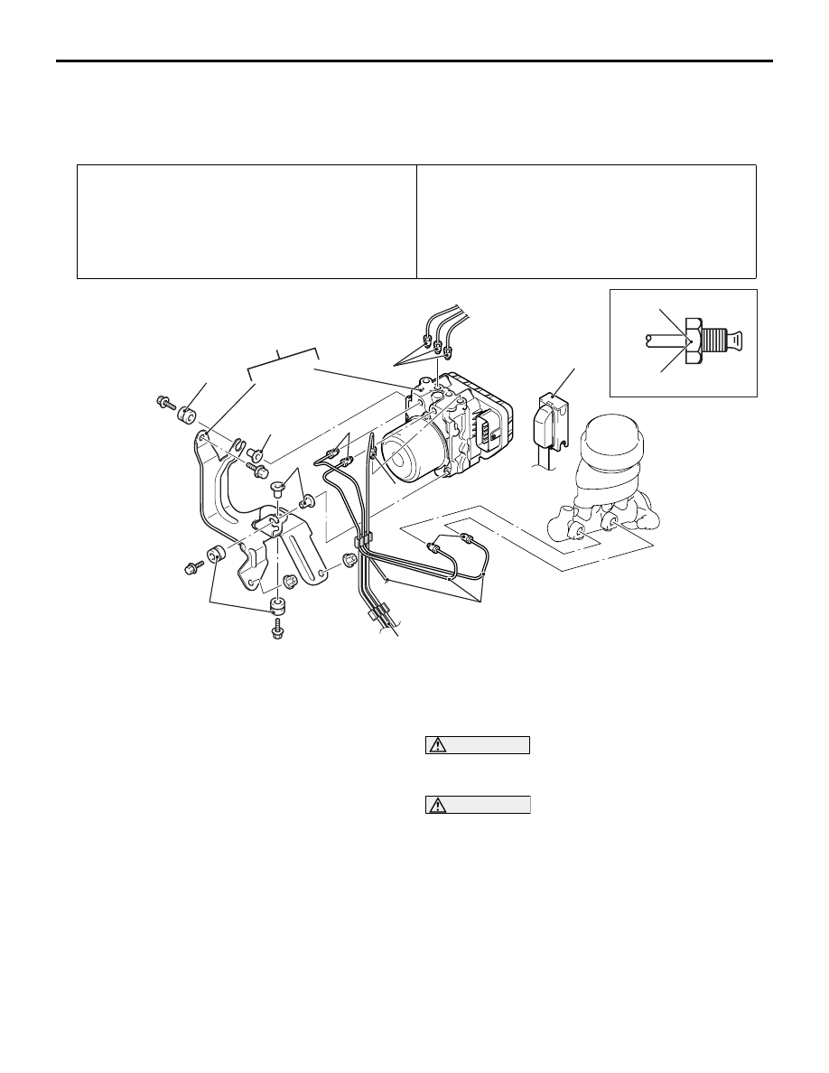
REMOVAL AND INSTALLATION
M1355005600862
NOTE: The ASTC-ECU is integrated in the hydraulic unit.
Pre-removal Operation
• Brake Fluid Draining
• Battery removal <LHD>
• Air cleaner removal (Refer to GROUP 15, Air Cleaner .)
Post-installation Operation
• Brake Fluid Filling
• Air cleaner installation (Refer to GROUP 15, Air Cleaner .)
• Battery installation <LHD>
• Brake Line Bleeding (Refer to GROUP 35A, On-vehicle
Service
− Bleeding .)
• Hydraulic Unit Check (Refer to .)
ACB00498
15 ± 2 N·m
2, 3
AC
7
4
2
3
1
2
2
<Vehicles for RHD>
<Vehicles for LHD>
5
6
6
8
5
Removal steps
1. Harness connector
>>
A
<< 2. Brake pipe and hydraulic unit
assembly connection
3. Brake pipe and master cylinder
connection <RHD>
4. Hydraulic unit assembly and hydraulic
unit bracket assembly
5. Insulator
6. Collar
<<
A
>>
7. Hydraulic unit assembly (integrated
with ASTC-ECU)
8. Hydraulic unit bracket assembly
REMOVAL SERVICE POINT
<<A>> HYDRAULIC UNIT ASSEMBLY (INTE-
GRATED WITH ASTC-ECU) REMOVAL
WARNING
The hydraulic unit is heavy. Use care when
removing it.
CAUTION
• The hydraulic unit cannot be disassembled.
Never loosen its nuts or bolts.
• Do not drop or shock the hydraulic unit.
• Do not turn the hydraulic unit upside down or
lay it on its side.