Mitsubishi L200. Manual - part 469


  Index      Mitsubishi     Mitsubishi L200 - service repair manual 2012 year


Search            


Content   ..  467  468  469  470   ..


Mitsubishi L200. Manual - part 469


TROUBLESHOOTING

ACTIVE STABILITY & TRACTION CONTROL SYSTEM (ASTC)

35C-132

NOTE: 

*

:Vehicles with rear differential lock

When the ASTC-ECU shut off ABS operation.
When the diagnosis system stops the ASTC-ECU, 
the M.U.T.-III display data will be unreliable.

ACTUATOR TEST TABLE

M1355001600280

Using M.U.T.-III, the following actuators can be forci-
bly operated:

NOTE: 

.

ABS and ASTC are operated by ASTC-ECU.

When ASTC-ECU is disabled due to the fail-safe 
function, the actuator test cannot be performed.

The actuator test can be performed only when 
the vehicle is stationary.

While the actuator test is performed, the ABS 
warning lamp flashes at a rate of 2 Hz.

After the actuator test has been performed, the 
brake warning lamp, ABS warning lamp, ASTC 
indicator lamp, and ASTC OFF indicator lamp 
illuminate until the ignition switch is turned to ON 
again or the communication between M.U.T.-III 
and ASTC-ECU is terminated.

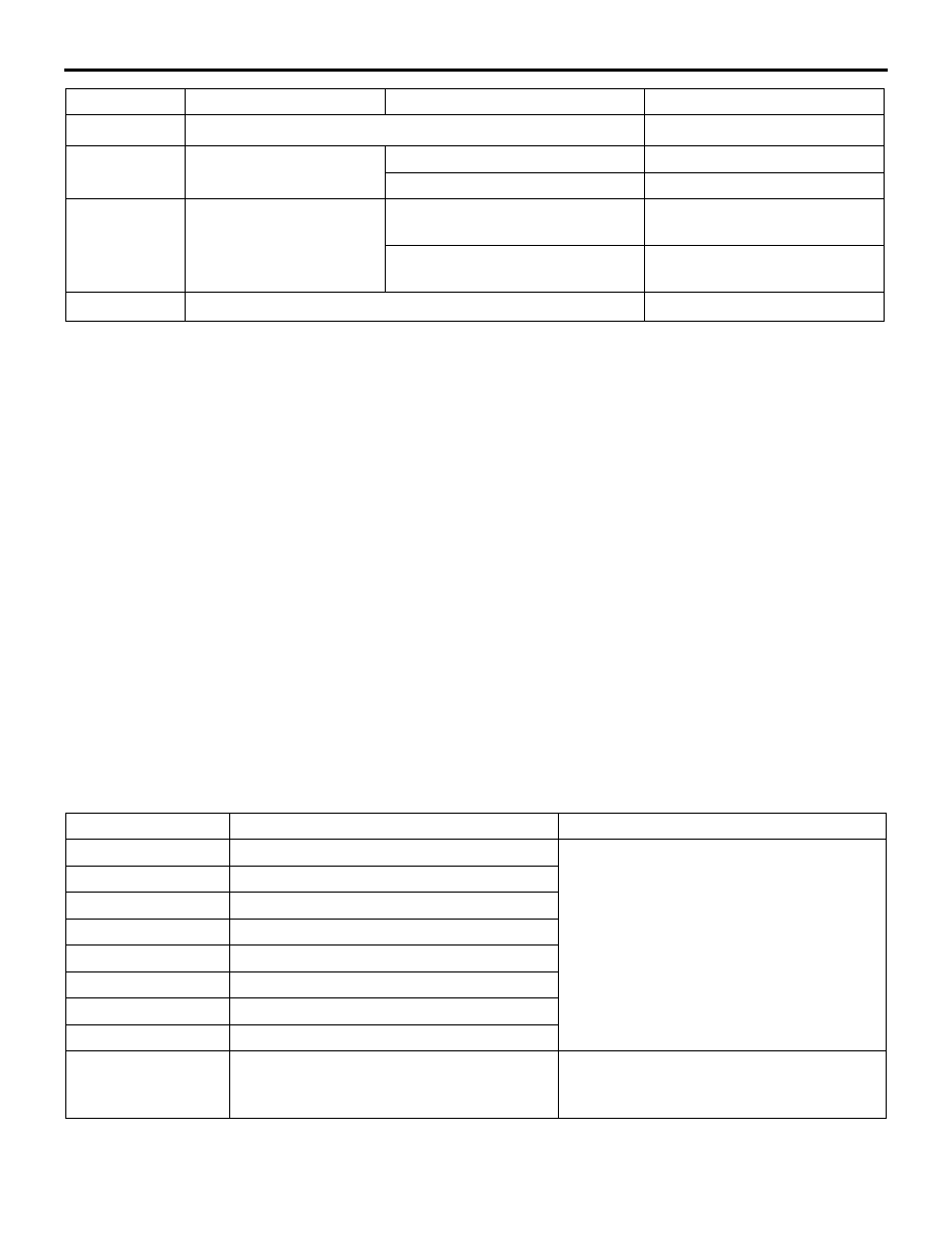
Actuator test specifications

Item No.

Check item

Driven component

01

FL wheel ABS drive

Solenoid valve for the corresponding 
channel of the hydraulic unit and pump 
motor (simplified inspection mode)

02

FR wheel ABS drive

03

RL wheel ABS drive

04

RR wheel ABS drive

05

FL wheel TCL drive

06

FR wheel TCL drive

07

RL wheel TCL drive

08

RR wheel TCL drive

09

Engine TCL Drive

Outputs the engine torque control signal 
(engine torque = 0 N

⋅m) to the engine 

ECU for three seconds.

58

G-sensor without Cal.

-20 to 20 m/s

2

61

ASC disable state

ASC switch: ON

Disable

ASC switch: OFF

Enable

63

*

Rear diff lock switch

When rear differential lock switch 
is ON

ON

When rear differential lock switch 
is OFF

OFF

64

Sum of ASC disable state

Item No.

Check item

Check condition

Normal condition

TROUBLESHOOTING

ACTIVE STABILITY & TRACTION CONTROL SYSTEM (ASTC)

35C-133

Operation pattern of items 01 to 08 

AC805556

1second

2 seconds

Approximately 0.05
seconds

Approximately 0.01
seconds

AB

End

M.U.T.-III actuator test
(Item No.05, 06, 07, 08) start

End

Close

Open

Increase in pressure

Steady pressure

Reduction in pressure

Drive

Stop

Liner valve
(ASTC)

Solenoid valve
(ABS)

Pump motor

M.U.T.-III actuator test
(Item No.01, 02, 03, 04) start

CHECK AT ASTC-ECU

M1355001700704

TERMINAL VOLTAGE CHECK CHART

AC800980

AG

Connector: A-48

(B)

1. Disconnect the ASTC-ECU connector A-48, and 

measure the voltages between terminal No.12 
and each terminal other than terminal No.24 as 
well as between terminal No.12 and each terminal 
other than terminal No.24.

2. The terminal layouts are shown in the illustrations 

below.

NOTE: Do not measure terminal voltage for approxi-
mately three seconds after the ignition switch is 
turned "ON." The ASTC-ECU performs the initial 
check during that period.

Terminal 
No.

Check item

Checking requirements

Normal condition

1

Solenoid valve power 
supply

Always

Battery voltage

3

ABS warning lamp 
output

Ignition switch: "ON" (When ABS warning lamp is 
ON.)

1 V or less

Ignition switch: "ON" (When ABS warning lamp is 
OFF.)

Approximately 
system voltage

TROUBLESHOOTING

ACTIVE STABILITY & TRACTION CONTROL SYSTEM (ASTC)

35C-134

NOTE: 

.

*1

: Vehicles with rear differential lock

*2

: Vehicles for M/T only

5

Brake warning lamp 
output

Ignition switch: "ON" (When brake warning lamp is 
ON.)

1 V or less

Ignition switch: "ON" (When the brake warning lamp 
is OFF, the brake fluid level is normal and the 
parking brake is "OFF" position.)

Approximately 
system voltage

7

Wheel speed sensor 
(FR) power supply

Ignition switch: "ON"

Approximately 
system voltage

9

Wheel speed sensor 
(RL) power supply

Ignition switch: "ON"

Approximately 
system voltage

10

ASC OFF lamp 
output

Ignition switch: "ON" (When ASC OFF switch is not 
pushed.)

1 V or less

Ignition switch: "ON" (When ASC OFF switch is 
pushed.)

Approximately 
system voltage

13

Motor power supply

Always

Battery voltage

19

Wheel speed sensor 
(FL) power supply

Ignition switch: "ON"

Approximately 
system voltage

21

Wheel speed sensor 
(RR) power supply

Ignition switch: "ON"

Approximately 
system voltage

22

ASC warning lamp 
output

Ignition switch: "ON" (When ASC warning lamp is 
ON.)

1 V or less

Ignition switch: "ON" (When ASC warning lamp is 
OFF.)

Approximately 
system voltage

25

ASTC-ECU power 
supply

Ignition switch: "ON" 

Battery voltage

Ignition switch: "OFF" 

1 V or less

26

Stop lamp switch 
input

Ignition switch: 
"ON" 

Stop lamp switch: "ON" 

Approximately 
system voltage

Stop lamp switch: "OFF" 

1 V or less

29

ASC switch output

Ignition switch: 
"ON" 

When the ASC OFF switch is 
not pushed (Not being 
operated)

Approximately 
system voltage

When the ASC OFF switch is 
pushed (being operated)

1 V or less

30

*1

Rear differential lock 
detection switch input

Rear differential lock detection switch: "OFF" 

Approximately 
system voltage

Rear differential lock detection switch: "ON" 

1 V or less

32

*2

Back-up lamp switch 
input

Ignition switch: 
"ON" 

Shift lever: Other than reverse 
position

Approximately 
system voltage

Shift lever: Reverse position

1 V or less

Terminal 
No.

Check item

Checking requirements

Normal condition

ON-VEHICLE SERVICE

ACTIVE STABILITY & TRACTION CONTROL SYSTEM (ASTC)

35C-135

RESISTANCE AND CONTINUITY BETWEEN 
HARNESS-SIDE CONNECTOR TERMINALS

AC800980

AG

Connector: A-48

(B)

1. Disconnect the A-48 ASTC-ECU connector.
2. Measure the resistance and continuity between 

the terminals indicated in the table below.

Terminal No.

Signal

Normal condition

12 to body earth

Earth

Continuity exists (2 

Ω or less)

24 to body earth

Earth

Continuity exists (2 

Ω or less)

ON-VEHICLE SERVICE

WHEEL SPEED SENSOR OUTPUT 
CURRENT MEASUREMENT

M1355027300104

Refer to GROUP 35B 

− Wheel Speed Sensor Output 

Current Measurement .

HYDRAULIC UNIT CHECK

M1355006100075

CAUTION

• The roller of the braking force tester and the 

tyre should be dry during testing.

• When testing the front brakes, apply the park-

ing brake. When testing the rear brakes, stop 
the front wheels with chocks.

1. Jack up the vehicle. Then support the vehicle with 

rigid racks at the specified jack-up points or place 
the front or rear wheels on the rollers of the 
braking force tester.

2. Release the parking brake, and feel the drag force 

(drag torque) on each road wheel. When using 
the braking force tester, take a reading of the 
brake drag force.

CAUTION

Before connecting or disconnecting the M.U.T.-
III, turn the ignition switch to the "LOCK" (OFF) 
position.
3. Connect M.U.T.-III to the diagnosis connector.
4. After checking that the selector lever is in "P" 

range, start the engine.

5. Select "Interactive Diagnosis" from the start-up 

screen.

6. Select "System Select."
7. Choose "ABS/ASC/ASTC" from the "CHASSIS" 

tab.

8. Select "Actuator Test" from "ABS/ASC/ASTC" 

screen.

9. Choose an appropriate item for hydraulic unit 

check.
NOTE: The ASTC system will switch to the 
M.U.T.-III mode and the ABS warning lamp, ASTC 
indicator lamp and ASTC OFF indicator lamp will 
illuminates.
NOTE: When the ABS and ASTC has been inter-
rupted by the fail-safe function, M.U.T.-III actuator 
testing cannot be used.


Content   ..  467  468  469  470   ..