Mitsubishi L200. Manual - part 470
AC309090
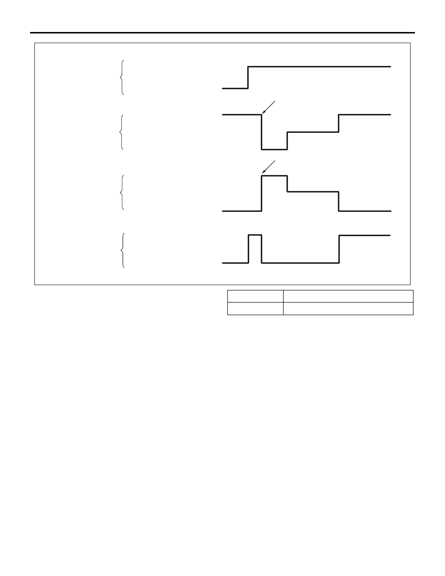
Depressed
Released
Pressure increase
Pressure decrease
Pressure hold
Lock
Drag force when the
pedal is free
Pedal operation
Solenoid valve
operation (ABS)
Solenoid valve
operation (ASC, ATC)
Checking the brake force
AD
M.U.T.-III actuator test
(Item No.01, 02, 03, 04) start
1 s
2 s
3 s
M.U.T.-III actuator test
(Item No.05, 06, 07, 08) start
2 s
1 s
Pressure increase
Pressure decrease
Pressure hold
ON-VEHICLE SERVICE
ACTIVE STABILITY & TRACTION CONTROL SYSTEM (ASTC)
35C-136
10.Turn the wheel by hand and check the change in
braking force when the brake pedal is depressed.
When using the braking force tester, depress the
brake pedal until the braking force is at the
following values, and check that the braking force
changes to the brake drag force reading taken in
step 2 when the actuator is force-driven. The
result should be as shown in the diagram above.
Front wheel
785
− 981 N
Rear wheel
588
− 784 N
11.If the result of inspection is abnormal, repair
according to the Diagnosis Table below.