Mitsubishi L200. Manual - part 435


  Index      Mitsubishi     Mitsubishi L200 - service repair manual 2012 year


Search            


Content   ..  433  434  435  436   ..


Mitsubishi L200. Manual - part 435


HYDRAULIC UNIT

ANTI-SKID BRAKING SYSTEM (ABS)

35B-61

INSTALLATION SERVICE POINT

>>A<< BRAKE PIPE AND HYDRAULIC UNIT CON-
NECTION

ACB00743 AC

6

5

4

3

2

1

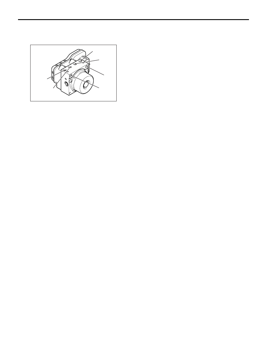
Connect the pipes to the hydraulic unit assembly as 
shown in the illustration.
1. From the master cylinder (primary)
2. To the front brake (LH)
3. To the rear brake (RH)
4. To the rear brake (LH)
5. To the front brake (RH)
6. From the master cylinder (secondary)

WHEEL SPEED SENSOR

ANTI-SKID BRAKING SYSTEM (ABS)

35B-62

WHEEL SPEED SENSOR

REMOVAL AND INSTALLATION

M1352020700232

Post-installation Operation
• Wheel Speed Sensor Output Current Measurement 

(Refer to 

P.35B-57

.)

AC503136AD

N

1

3

4

4

6

6

7

7

N

7

N

7

N

1

3

3

4

4

5

6

6

<2WD (Except HIGH RIDER)>

<2WD (HIGH RIDER) and 4WD>

<Front>

<Rear>

<Front>

<Rear>

2

2

Front wheel speed sensor 
removal steps 

1.

Bracket

2.

Equip nut

<<

A

>>

3.

Front wheel speed sensor

Front wheel speed sensor 
removal steps (Continued)

WHEEL SPEED SENSOR

ANTI-SKID BRAKING SYSTEM (ABS)

35B-63

NOTE: The front rotor is integrated with the BJ 
assembly, which cannot be disassembled. <2WD 
(High rider) and 4WD>

REMOVAL SERVICE POINT

<<A>> FRONT WHEEL SPEED SENSOR/REAR 
WHEEL SPEED SENSOR REMOVAL

AC505455AB

Wheel speed sensor

CAUTION

Be careful when handling the projection at the tip 
of the wheel speed sensor and the toothed edge 
of the rotor so as not to damage them by contact-
ing other parts.

INSPECTION

M1352020800176

WHEEL SPEED SENSOR CURRENT 
CHECK

CAUTION

• Do not connect the battery terminals in 

reverse as the wheel speed sensor may be 
damaged.

ACB00832

MB992006

AB

When the current value is measured by the 
wheel speed sensor connector, measure it 
with the wheel speed sensor installed in the 
vehicle.

1. Connect the circuit tester to the wheel speed 

sensor using the special tool extra fine probe 
(MB992006), and measure the sensor current as 
a single unit.

Standard value: 5 to 9 mA or 11 to 17 mA

2. If the measurement value is not within the 

standard value range, replace the wheel speed 
sensor with a new one.

4.

Protector

Front rotor [Refer to GROUP 26, 
Front Axle Hub Assembly . <2WD 
(Except High rider)> or GROUP 26, 
Drive Shaft Assembly . <2WD (High 
rider), 4WD>]
Rear wheel speed sensor 
removal steps 

5.

Harness

<<

A

>>

6.

Rear wheel speed sensor

7.

O-ring

Rear rotor (Refer to GROUP 27, 
Axle Shaft Assembly .)

Front wheel speed sensor 
removal steps (Continued)

G-SENSOR <4WD>

ANTI-SKID BRAKING SYSTEM (ABS)

35B-64

WHEEL SPEED SENSOR INSULATION CHECK

AC505456

1. Connect the circuit tester to the wheel speed 

sensor using the special tool extra fine probe 
(MB992006), and measure the insulation 
resistance between the terminal No. 1/2 and the 
wheel speed sensor body as a single unit.

Standard value: 1.5 M

 or more

2. If the insulation resistance is not within the 

standard value range, replace the wheel speed 
sensor with a new one.

TOOTHED ROTOR CHECK

AC000965

Check whether the rotor teeth are broken or 
deformed. Replace the driveshaft assembly for the 
front side, or the retainer for the rear side, respec-
tively, if the teeth are damaged or deformed.

G-SENSOR <4WD>

REMOVAL AND INSTALLATION

M1352010100604

CAUTION

Do not drop or apply a shock on the G-sensor.

Pre-removal and Post-installation Operation
• Rear Floor Console Assembly removal and installation 

(Refer to GROUP 52A 

− Rear Floor Console Assembly .)

• Front Floor Console Assembly removal and installation 

(Refer to GROUP 52A 

− Front Floor Console Assembly .)

AC712088AB

2

1

Removal steps 

1. Harness connector
2. G-sensor


Content   ..  433  434  435  436   ..