Mitsubishi L200. Manual - part 436
G-SENSOR <4WD>
ANTI-SKID BRAKING SYSTEM (ABS)
35B-65
INSPECTION
M1352018000117
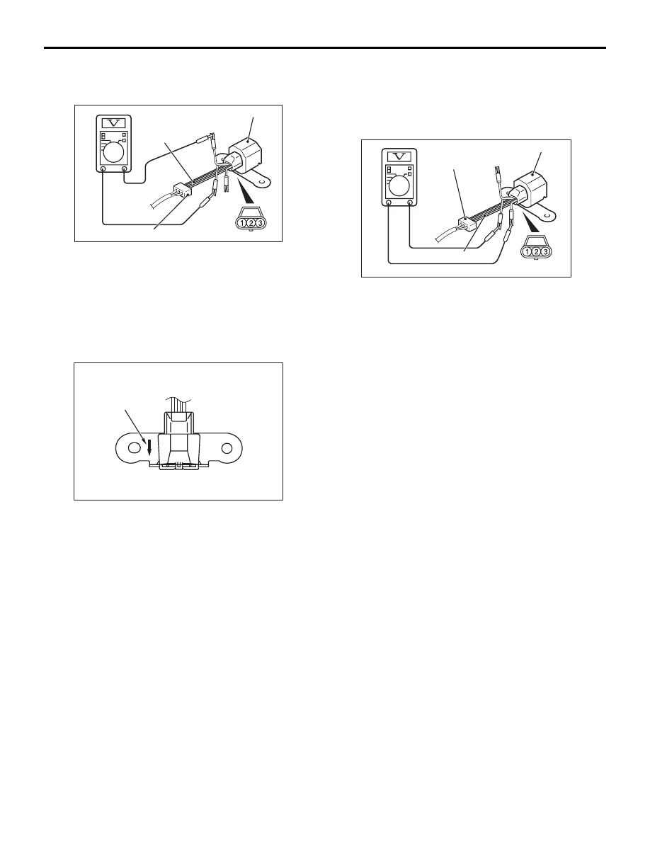
G-SENSOR CHECK
AC505459
MB991348
Connector: C-128 (Harness side)
G-sensor
AB
1. Disconnect the G-sensor connector and connect
special tool test harness set (MB991348),
between terminals of the disconnected connector.
2. With the ignition switch turned to the "ON"
position, read the voltage between terminals
number 1 and 2.
Standard value: 2.4
− 2.6 V
AC505460AB
Arrow mark
3. With special tool test harness set (MB991348)
connected, rotate so that the arrow mark straight
down. Read output voltage between terminals
number 1 and 2.
Standard value: 3.55
− 3.95 V
AC505461
MB991348
Connector: C-128
(Harness side)
G-sensor
AB
4. When the measured values in step 2 and step 3
are not within the standard value, measure the
voltage between terminal No. 3 and terminal No.
1.
Standard value: 4.75
− 5.25 V
NOTE: When there is an open or short circuit in
the G-sensor circuit, the power supply to the G-
sensor is stopped in approximately 2 seconds
after the ignition switch is turned on.
5. If the measured values in step 2 and step 3 are
out of the standard value and the measured value
in step 4 is within the standard value, replace the
G-sensor.
6. When all the measured values in steps 2, 3 and 4
are out of the standard value, check the wiring
harness and repair if necessary. When the wiring
harness is normal, the ABS-ECU may be
defective.