Mitsubishi L200. Manual - part 434


  Index      Mitsubishi     Mitsubishi L200 - service repair manual 2012 year


Search            


Content   ..  432  433  434  435   ..


Mitsubishi L200. Manual - part 434


ON-VEHICLE SERVICE

ANTI-SKID BRAKING SYSTEM (ABS)

35B-57

ON-VEHICLE SERVICE

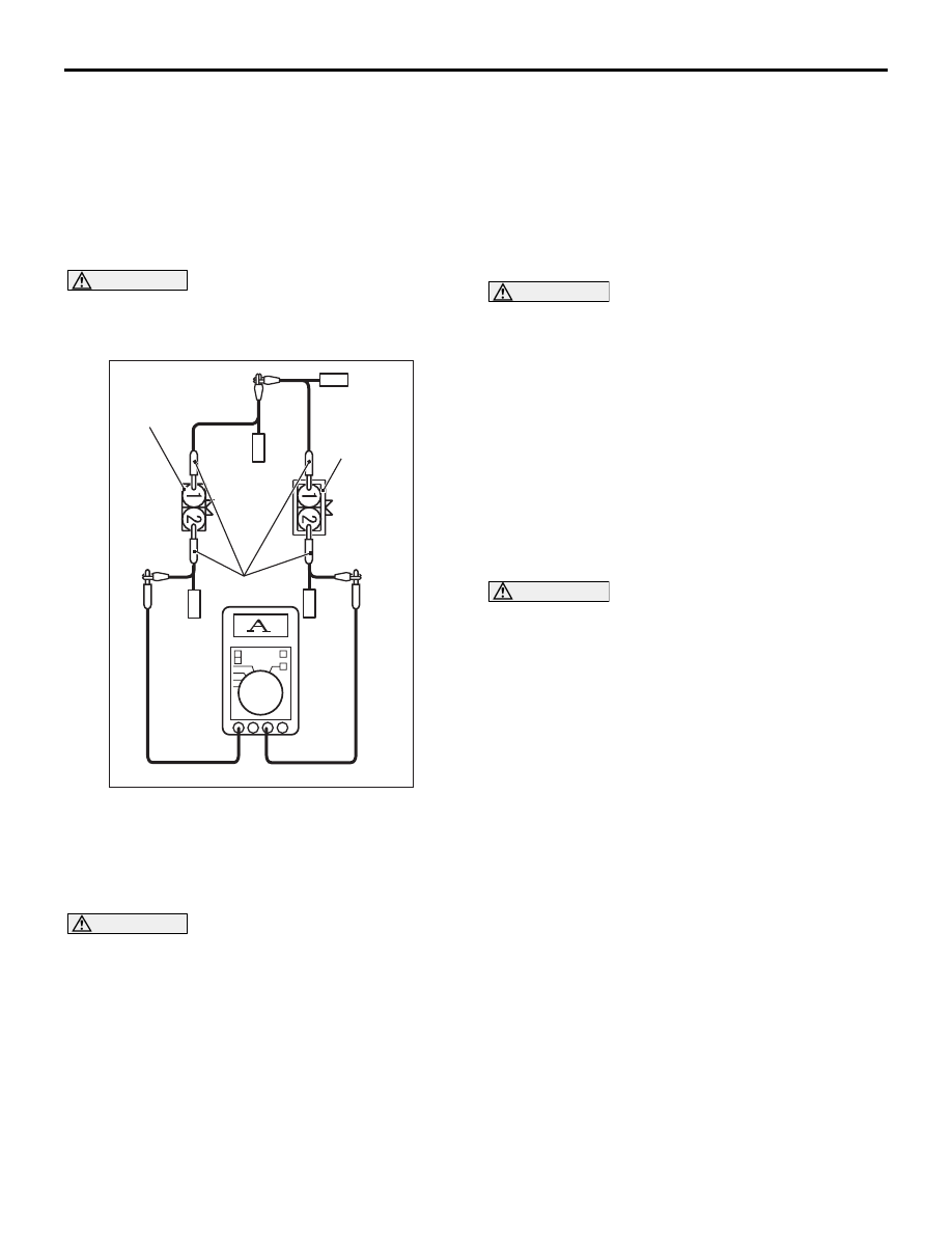
WHEEL SPEED SENSOR OUTPUT 
CURRENT MEASUREMENT

M1352032800065

The relevant wheel, on which the wheel speed sen-
sor is fitted, should be free to run.
1. Remove the wheel speed sensor connector to be 

checked.

CAUTION

For precise measurement, do not connect to the 
wheel speed sensor-side connector and the wir-
ing harness side connector terminal No.1.

ACB00833

MB991709

AB

Wheel speed 
sensor
connector

Harness
connector

2. Use the special tool test harness (MB991709) to 

connect a multimeter between the wheel speed 
sensor-side connector and the wiring harness 
connector terminal No.2.

3. Turn the ignition switch to the "ON" position.

CAUTION

Do not rotate the wheel too quickly. Output cur-
rent changes significantly as the wheel speed 
detection magnetic encoder comes near or goes 
away from the wheel speed sensor.
4. Rotate the wheel, on which the wheel speed 

sensor is fitted, quite slowly to measure the output 
current with the multimeter.

Standard value: 5 to 9 mA or 11 to 17 mA

5. If the measurement is not within the standard 

value, or the output current does not change in 
proportion to the wheel rotation, replace the wheel 
speed sensor (Refer to 

P.35B-62

).

HYDRAULIC UNIT CHECK

M1352001701106

CAUTION

• The roller of the braking force tester and the 

tyre should be dry during testing.

• When testing the front brakes, apply the park-

ing brake. When testing the rear brakes, stop 
the front wheels with chocks.

1. Jack up the vehicle. Then support the vehicle with 

rigid racks at the specified jack-up points or place 
the front or rear wheels on the rollers of the 
braking force tester.

2. Release the parking brake, and feel the drag force 

(drag torque) on each road wheel. When using 
the braking force tester, take a reading of the 
brake drag force.

CAUTION

To prevent damage to M.U.T.-III, always turn the 
ignition switch to the "LOOK" (OFF) position 
before connecting or disconnecting the M.U.T.-III.
3.  Turn the ignition switch to the "LOCK" (OFF) 

position and set the M.U.T.-III as shown in the 
illustration.

4. After checking that the selector lever is in neutral, 

start the engine.

5. Use the M.U.T.-III to force-drive the actuator.

NOTE: The ABS system will switch to the M.U.T.-
III mode and the ABS warning lamp will illuminate.
NOTE: When the ABS has been interrupted by 
the fail-safe function, the M.U.T.-III actuator test-
ing cannot be used.

AC000954AL

M.U.T.-III actuator test
(Item No.01, 02, 03, 04) start

1 second

2 second

3 second

Depressed

Released

Increase in pressure

Reduction in pressure

Steady pressure

Lock

Drag force when the
pedal is free

Pedal
operation

Solenoid
valve
position

Checking
the brake
force

Approx. 0.05 second

ON-VEHICLE SERVICE

ANTI-SKID BRAKING SYSTEM (ABS)

35B-58

6. Turn the wheel by hand and check the change in 

braking force when the brake pedal is depressed. 
When using the braking force tester, depress the 
brake pedal until the braking force is at the 
following values, and check that the braking force 
changes to the brake drag force inspected in step 
2 when the actuator is force-driven. The result 
should be as shown in the diagram above.

Front wheel

785 to 981 N

Rear wheel

588 to 784 N

7. If the result of inspection is abnormal, repair 

according to the Diagnosis Table below.

Diagnosis table
M.U.T.-III display

Operation

Inspection 
result

Judgeme
nt

Probable 
cause

Remedy

1 FL wheel ABS drive
2 FR wheel ABS drive
3 RL wheel ABS drive
4 RR wheel ABS drive

• Depress brake 

pedal to lock 
wheel.

• Using the M.U.T.-

III, select the 
wheel to be 
checked and 
force the actuator 
to operate.

• Turn the selected 

wheel manually to 
check the change 
of brake force.

Brake force is 
released for 
three 
seconds after 
wheels have 
been locked.

Normal

Wheel does 
not lock when 
brake pedal is 
depressed.

Abnormal Clogged brake 

line other than 
hydraulic unit

Check and 
clean brake line

Clogged 
hydraulic circuit 
in hydraulic unit

Replace 
hydraulic unit 
assembly

Brake force is 
not released

Incorrect 
hydraulic unit 
brake tube 
connection

Connect 
correctly

Hydraulic unit 
solenoid valve 
not functioning 
correctly

Replace 
hydraulic unit 
assembly

8. After inspection, disconnect the M.U.T.-III 

immediately after turning the ignition switch to the 
"LOCK" (OFF) position. 

ON-VEHICLE SERVICE

ANTI-SKID BRAKING SYSTEM (ABS)

35B-59

Hydraulic unit installation adjustment
Refer to 

P.35B-60

.

1. Operate the pre-removal steps for the hydraulic 

unit.

2. Remove all brake tubes.
3. Loosen the mounting bolt and nut of the hydraulic 

unit bracket.

4. Install all brake tubes temporarily.
5. Shake hydraulic unit to all directions with both 

hands to make the hydraulic unit bracket insulator 
fit with the unit.

6. Install the the hydraulic unit bracket with mounting 

bolt and nut not to load the brake tube.

7. Install all brake tubes securely.

NOTE: Install the flare nut taking care not to let 
the brake tube turn together.

8. Operate the post-installation steps of the hydraulic 

unit.

IN THE EVENT OF A DISCHARGED 
BATTERY

M1352003500484

WARNING

If the ABS is not operating, the vehicle pos-
ture will be unstable during braking, Do not 
drive the vehicle with the ABS-ECU connec-
tor disconnected or with the ABS not operat-
ing for any other reason.

If the engine is started using a booster cable when 
the battery is completely flat, and the vehicle is then 
driven without waiting for the battery to be recharged, 
the engine may misfire and it may not be possible to 
drive the vehicle. This is because the ABS consumes 
a large amount of current when carrying out its initial 
checks. If this happens, recharge the battery fully.

HYDRAULIC UNIT

ANTI-SKID BRAKING SYSTEM (ABS)

35B-60

HYDRAULIC UNIT

REMOVAL AND INSTALLATION

M1352008601199

NOTE: The ABS-ECU is integrated in the hydraulic unit.

Pre-removal Operation
• Brake Fluid Draining

Post-installation Operation
• Brake Fluid Filling

• Brake Line Bleeding (Refer to GROUP 35A, On-vehicle 

Service 

− Bleeding .)

• Hydraulic Unit Check (Refer to 

P.35B-57

.)

ACB00499 AB

2

15 ± 2 N·m

2, 3

2

<Vehicles for LHD>

<Vehicles for RHD>

1

2

9

8

5

7

6

3

4

Removal steps 

1. Harness connector

>>

A

<< 2. Brake pipe and hydraulic unit 

assembly connection

3. Brake pipe and master cylinder 

connection <RHD>

4. Brake pipe <RHD>
5. Hydraulic unit assembly and hydraulic 

unit bracket assembly

6. Insulator
7. Collar

<<

A

>>

8. Hydraulic unit assembly (integrated 

with ABS-ECU)

9. Hydraulic unit bracket assembly

REMOVAL SERVICE POINT

<<A>> HYDRAULIC UNIT ASSEMBLY (INTE-
GRATED WITH ABS-ECU) REMOVAL

WARNING

The hydraulic unit is heavy. Use care when 
removing it.

CAUTION

• The hydraulic unit cannot be disassembled. 

Never loosen its nuts or bolts.

• Do not drop or shock the hydraulic unit.
• Do not turn the hydraulic unit upside down or 

lay it on its side.


Content   ..  432  433  434  435   ..