Mitsubishi L200. Manual - part 338
AKX00151
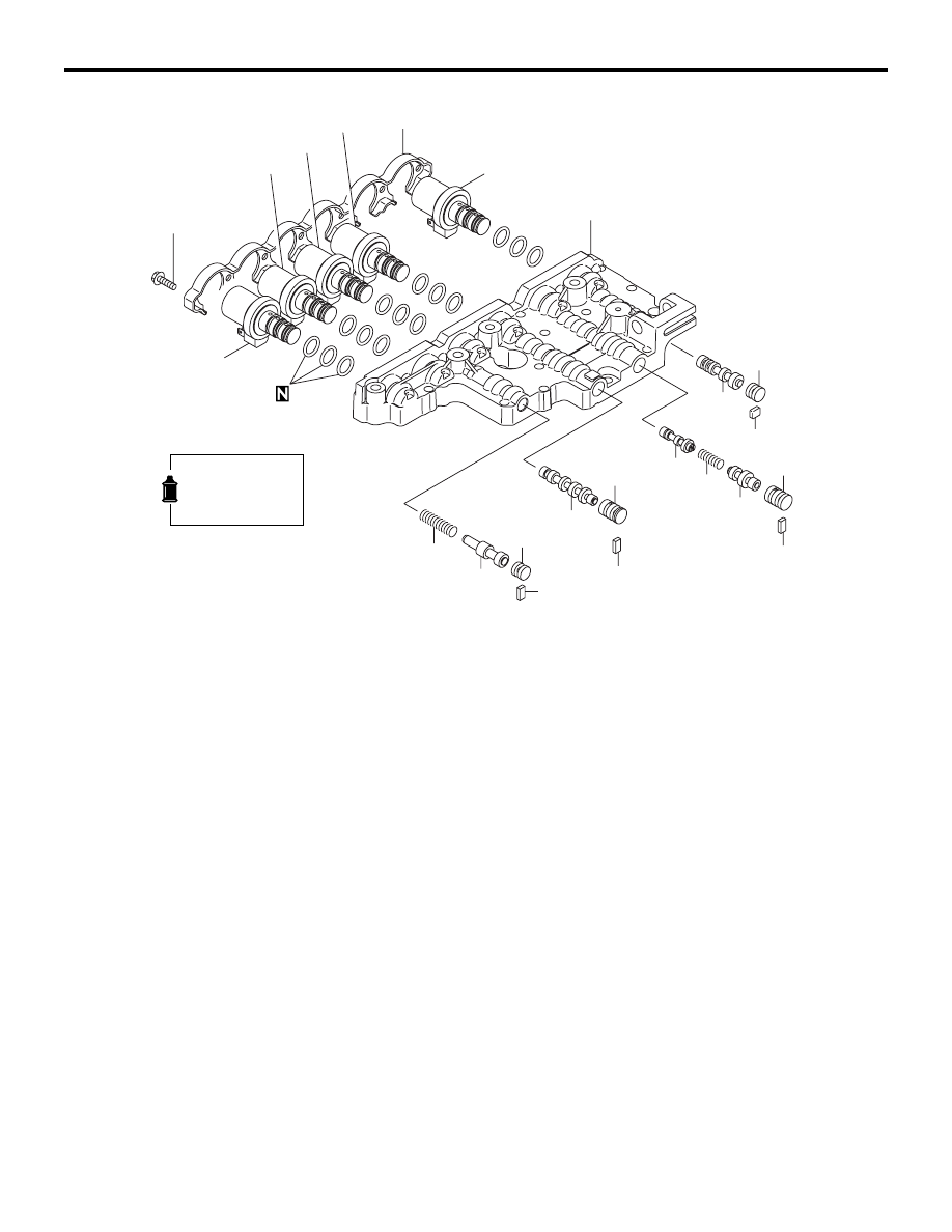
17
18
19
20
25
26
27
22
23
24
28
29
30
21
35
36
37
32
33
34
38
31
Apply automatic
transmission fluid
to all moving parts
before installation.
6.0 ± 1.0 N·m
AC
Disassembly steps
17. Solenoid support
<<
A
>>
>>
A
<<
18. Low reverse brake solenoid valve
<<
A
>>
>>
A
<<
19. Second brake solenoid valve
<<
A
>>
>>
A
<<
20. Underdrive clutch solenoid valve
<<
A
>>
>>
A
<<
21. Overdrive clutch solenoid valve
<<
A
>>
>>
A
<<
22. Torque converter clutch control
solenoid valve
23. Stopper plate
24. Stopper plug
25. Switching valve
26. Stopper plate
27. Fail-safe valve a sleeve
28. Fail-safe valve A2
29. Fail-safe valve A spring
30. Fail-safe valve A1
31. Stopper plate
32. Fail-safe valve B sleeve
33. Fail-safe valve B
34. Stopper plate
35. Stopper plug
36. Torque converter pressure control
valve
37. Torque converter pressure control
valve spring
38. Upper valve body
VALVE BODY
AUTOMATIC TRANSMISSION OVERHAUL <V4A5>
23C-61
Disassembly steps (Continued)