Mitsubishi L200. Manual - part 337
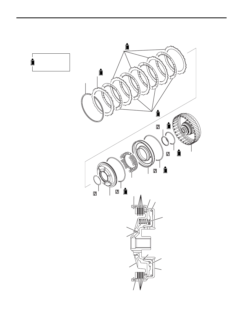
UNDERDRIVE CLUTCH
AUTOMATIC TRANSMISSION OVERHAUL <V4A5>
23C-57
UNDERDRIVE CLUTCH
DISASSEMBLY AND REASSEMBLY
M1233027300284
AK700896
4
5
6
1
2
3
7
8
9
11
12
13
10
4
5
6
1
2
3
7
8
9
11
12
13
10
AB
Apply automatic
transmission fluid
to all moving parts
before installation.