Mitsubishi L200. Manual - part 336


  Index      Mitsubishi     Mitsubishi L200 - service repair manual 2012 year


Search            


Content   ..  334  335  336  337   ..


Mitsubishi L200. Manual - part 336


SECOND BRAKE

AUTOMATIC TRANSMISSION OVERHAUL <V4A5>

23C-53

1. Install the snap ring in the reverse clutch retainer 

groove.

2. Set special tools as shown in the illustration, and 

compress the clutch element.

• Spring compressor (MB991789)

• Spring compressor retainer (MD998924)

3. Check that the clearance between the snap ring 

and the clutch reaction plate is within the standard 
valus.If not within the standard value, select a 
snap ring to adjust.

Standard value: 1.5 

 1.7 mm

(For reverse clutch end play)
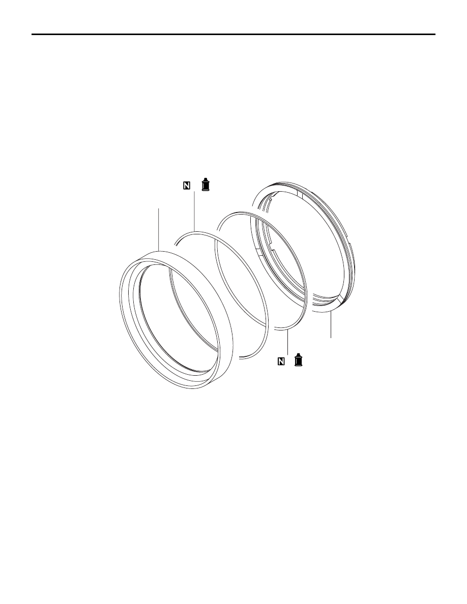
SECOND BRAKE

DISASSEMBLY AND REASSEMBLY

M1233021800269

AKX00134

1

2

3

4

AB

Disassembly steps 

1.

Second brake retainer

2.

Second brake piston

>>

A

<<

3.

D-ring

>>

A

<<

4.

D-ring

REASSEMBLY SERVICE POINT

>>A<< D-RING INSTALLATION
1. Apply ATF to the D-ring.
2. Install the D-ring in the grooves on the outer and 

inner periphery of the piston. Make sure that the 
D-ring is not twisted or damaged when installing.

LOW REVERSE ANNULUS GEAR

AUTOMATIC TRANSMISSION OVERHAUL <V4A5>

23C-54

LOW REVERSE ANNULUS GEAR

DISASSEMBLY AND REASSEMBLY

M1233027100268

AKX00135

4

5

6

1

2

3

7

8

9

10

AC

Apply automatic
transmission fluid
to all moving parts
before installation.

Disassembly steps 

1.

Snap ring

2.

Overdrive planetary carrier

>>

D

<<

3.

Thrust bearing No.5

4.

Underdrive sun gear

>>

C

<<

5.

Thrust bearing No.6

6.

Output planetary carrier

>>

B

<<

7.

Stopper plate

>>

A

<<

8.

One-way clutch

9.

Snap ring

10. Low/reverse annulus gear

REASSEMBLY SERVICE POINTS

>>A<< ONE-WAY CLUTCH INSTALLATION

AK403387AB

Arrow

Install the one-way clutch so that the arrow stamp is 
oriented as shown in the illustration.

>>B<< STOPPER PLATE INSTALLATION

AK403388AB

Claw

Groove

Stopper plate

Install the stopper plate onto the low/reverse annulus 
gear. Make sure that the stopper plate claw is 
securely engaged in the annulus gear groove.

CENTRE SUPPORT

AUTOMATIC TRANSMISSION OVERHAUL <V4A5>

23C-55

>>C<< THRUST BEARING No.6 INSTALLATION

CAUTION

Make sure thrust bearing No.6 is mounted in the 
correct direction.

AKX00138

Output planetary
carrier side

AC

Apply vaseline or petroleum jelly on the thrust bear-
ing No.6, and then install onto the output planetary 
carrier.

>>D<< THRUST BEARING No.5 INSTALLATION

CAUTION

Make sure thrust bearing No.5 is mounted in the 
correct direction.

AKX00139

Overdrive planetary 
carrier side

AC

Apply vaseline or petroleum jelly on the thrust bear-
ing No.5, and then install on the overdrive planetary 
carrier.

CENTRE SUPPORT

DISASSEMBLY AND REASSEMBLY

M1233010000195

AKX00140

4

5

6

1

2

3

7

8

9

10

AC

Apply automatic
transmission fluid
to all moving parts
before installation.

Disassembly steps 

<<

A

>>

>>

C

<<

1.

Snap ring

2.

Plate

3.

One-way clutch inner race

>>

B

<<

4.

O-ring

Disassembly steps (Continued)

CENTRE SUPPORT

AUTOMATIC TRANSMISSION OVERHAUL <V4A5>

23C-56

DISASSEMBLY SERVICE POINT

<<A>> SNAP RING REMOVAL

AK403389AB

Snap ring

MB991630

MD998924

1. Set special tools as shown in the illustration so 

that they are pressed against the inner race of the 
one-way clutch.

• Spring compressor (MB991630)

• Spring compressor retainer (MD998924)

2. Screw in the special tool nut, and lightly press 

against the inner race of the one-way clutch.

3. Remove the snap ring.

REASSEMBLY SERVICE POINTS

>>A<< D-RING INSTALLATION
1. Apply ATF to the D-ring.
2. Install the D-ring in the grooves on the outer and 

inner periphery of the piston. Make sure that the 
D-ring is not twisted or damaged when installing.

>>B<< O-RING INSTALLATION

AK403390AB

O-ring

Install the O-ring onto the center support at the posi-
tion shown in the illustration.

>>C<< SNAP RING INSTALLATION

AK403389AB

Snap ring

MB991630

MD998924

1. Set special tools as shown in the illustration.

• Spring compressor (MB991630)

• Spring compressor retainer (MD998924)

2. Screw in the special tool nut, and lightly press 

against the inner race of the one-way clutch.

3. Install the snap ring.

5.

Spring retainer

6.

Return spring

7.

Low/reverse brake piston

>>

A

<<

8.

D-ring

>>

A

<<

9.

D-ring

10. Center support

Disassembly steps (Continued)


Content   ..  334  335  336  337   ..