Mitsubishi L200. Manual - part 335
AK403457AB
Transmission
side
Identification
symbol A
TRANSMISSION
AUTOMATIC TRANSMISSION OVERHAUL <V4A5>
23C-49
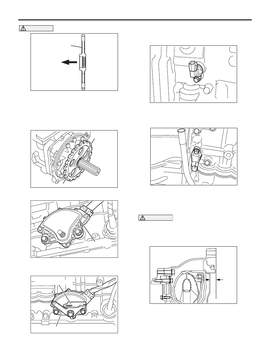
CAUTION
• Install the parking gear so that the side with-
out the spline cut faces the transmission side.
• Heat the parking gear to 160 − 180 °C and
shrink fit up to the stepped section of the out-
put shaft. Do not heat for longer than neces-
sary at this time.
AK403344AB
Snap ring
Parking gear
65.Install the parking gear and snap ring.
AK601368AC
Inhibitor switch
66.Install the inhibitor switch, and fix the fastening
bolts temporarily.
AK403343
Inhibitor switch
Manual control lever
AB
67.Install the manual control lever.
68.Tighten the manual control lever mounting bolts to
the specified torque 21.5
± 3.5 N⋅m.
AK403342
69.Install the output shaft speed sensor.
70.Tighten the output shaft speed sensor mounting
bolts to the specified torque 11
± 1 N⋅m.
AK403341
71.Install the input shaft speed sensor.
72.Tighten the input shaft speed sensor mounting
bolts to the specified torque 11
± 1 N⋅m.
CAUTION
Apply ATF to the oil pump drive hub before
installing the torque converter. Be careful not to
damage the oil seal lip when installing the torque
converter.
AK403458AB
A
73.Install the torque converter, and secure it so that
the dimension (A) indicated in the illustration
meets the reference value.
Reference value: 20.9 mm