Mitsubishi L200. Manual - part 235


  Index      Mitsubishi     Mitsubishi L200 - service repair manual 2012 year


Search            


Content   ..  233  234  235  236   ..


Mitsubishi L200. Manual - part 235


EMISSION CONTROL

ENGINE AND EMISSION CONTROL

17-44

If the PM accumulates more than the standard, the 
engine-ECU carries out the control that automatically 
regenerates the DPF under certain conditions to 
remove the PM. At the DPF regeneration, the DPF 
temperature gets high and high temperature exhaust 
gases are given off.
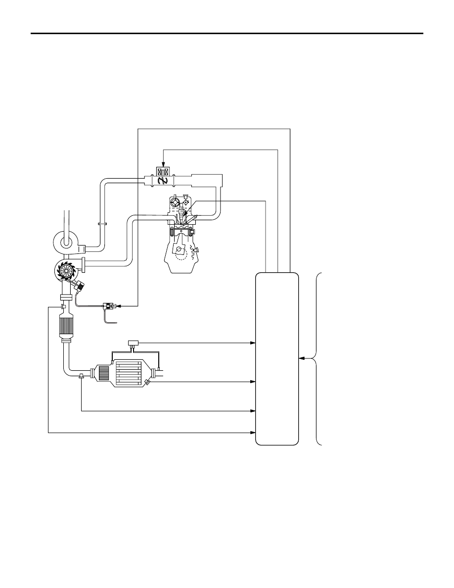
SYSTEM DIAGRAM

AKB00299

Engine-ECU

Rail pressure sensor

Accelerator pedal position
sensor

Vehicle speed sensor

AB

Air flow sensor

No. 1 intake air temperature
sensor 

EGR gas temperature sensor 

Crank angle sensor

Engine coolant temperature
sensor

Manifold absolute pressure
sensor

Injector

No. 1 exhaust gas temperature sensor

No. 2 exhaust gas temperature sensor
(catalyst temperature)

No. 3 exhaust gas temperature 
sensor (DPF temperature)

Exhaust differential 
pressure sensor

Catalytic
converter

Catalytic
converter

DPF

Variable geometry
control solenoid valve

Throttle valve control
servo (DC motor)

EMISSION CONTROL

ENGINE AND EMISSION CONTROL

17-45

DPF LAMP

AKB00242

DPF lamp

AB

When the engine oil level or the amount of accumu-
lated PM within the DPF exceeds the specified value, 
the DPF lamp is lit or blinked. When the vehicle is 
brought into the shop with the DPF lamp blinked, 
service the vehicle in accordance with the following 
procedures. 

DPF 
lamp

Engine 
warning 
lamp

State and service

Being 
blinked

Being lit

Carry out the forcible DPF 
regeneration using M.U.T.-III 
because PM being 
excessively accumulated 
within DPF is assumed. 
(Refer to 

P.17-46

)

Being 
blinked

Not 
being lit

Replace engine oil because 
engine oil level excessively 
increasing is assumed. (Refer 
to GROUP 12 

− On-vehicle 

service 

− Engine Oil 

Replacement )

After turning the ignition switch to "ON" position, the 
DPF lamp is lit for the purpose of the operational 
check for about 5 seconds.

COMPONENT LOCATION (DPF SYSTEM)

M1175006700138

AKB00300 AB

No. 1 exhaust gas
temperature sensor

AKB00301

No. 2 exhaust gas
temperature sensor
(catalyst temperature)

No. 2 exhaust gas
temperature sensor
(catalyst temperature)
connector

AB

AKB00302 AB

No. 3 exhaust gas
temperature sensor
(DPF temperature)

No. 3 exhaust gas
temperature sensor
(DPF temperature)
connector

AKB00303AB

Exhaust differential
pressure sensor

EMISSION CONTROL

ENGINE AND EMISSION CONTROL

17-46

FORCIBLE DPF REGENERATION

M1175006800221

WARNING

When the forcible DPF regeneration is car-
ried out, confirm that no people or no com-
bustible material is within its vicinity. If 
people or combustible material is around the 
muffler, serious injury or damage such as 
heat injury or fires may occur because high 
temperature exhaust gases are put out.

WARNING

Perform the forcible DPF regeneration in a 
well-ventilated and flat place when the vehi-
cle is stopped (If perform the forcible DPF 
regeneration indoors, surely carry out 
enforced ventilation).

WARNING

If the engine warning lamp is lit, the DPF sys-
tem might be abnormal. Carry out the inspec-
tion chart for diagnosis code, and then 
perform the forcible DPF regeneration (Refer 
to , GROUP 13A 

 Troubleshooting 

 Inspec-

tion Chart For Diagnosis codes).

Set the vehicle to the pre-inspection condition.

CAUTION

Connection and disconnection of M.U.T.-III 
should be always performed with the ignition 
switch turned to the "LOCK" (OFF) position.

AC509179

AB

Diagnosis

connector

MB991827

MB991824 

MB991910

<LH drive vehicles>

AC501413AC

Diagnosis

connector

MB991827

MB991824 

MB991910

<RH drive vehicles>

1. Connect the M.U.T.-III to the diagnosis connector.
2. Start the engine and let it run at idle.
3. From "FUNCTION MENU" on M.U.T.-III, select 

"SPECIAL FUNCTION".

4. From "SPECIAL FUNCTION", select "DPF 

REGENERATION".

EMISSION CONTROL

ENGINE AND EMISSION CONTROL

17-47

CAUTION

If the forcible regeneration of the DPF is carried 
out while the accumulated amount of the PM in 
the DPF exceeds the limit, the forcible regenera-
tion might not be correctly completed. This could 
be caused by the detection in the DPF system 
malfunction. Carry out the check procedure for 
the diagnosis code and solve the malfunction. 
(Refer to , GROUP 13A 

 Troubleshooting  

Inspection Chart For Diagnosis Codes)
5. Perform Item No. 33, DPF Regeneration.

NOTE: Carrying out the forcible DPF regeneration 
increases the engine speed 1,500 

 2,000 r/min 

(the temperature increases within the DPF and is 
maintained at approximately 600

°

C).

NOTE: When performed for about 25 minutes, the 
forcible DPF regeneration automatically stops. 
Depressing the accelerator pedal during the 
regeneration, however, can cancel the forcible 
DPF regeneration.
NOTE: If the DPF regeneration is carried out 
while the DPF lamp is illuminated or blinked due 
to the accumulated PM, the DPF lamp is turned 
off as soon as the forcible regeneration is cor-
rectly completed.

6. Turn the ignition switch to the "LOCK" (OFF) 

position and then remove the M.U.T.-III.

 No. 1 EXHAUST GAS TEMPERATURE 
SENSOR CHECK

M1175006900206

AKB00304

1 2

AB

No. 1 exhaust gas
temperature sensor

Equipment side
connector

1. Disconnect the No. 1 exhaust gas temperature 

sensor connector.

2. Measure resistance between terminals No. 1 and 

No. 2.

Standard value: 120 

 560 k (at 20°C)

3. Remove the No. 1 exhaust gas temperature 

sensor.

AKB00243

Exhaust gas
temperature sensor 

AB

4. Measure resistance while heating the sensor 

using a hair drier.

Normal condition:

Temperature (

°C)

Resistance (k

)

Higher

Smaller

5. If the value deviates from the standard value or 

the resistance remains unchanged, replace the 
No. 1 exhaust gas temperature sensor assembly.

6. Install the No. 1 exhaust gas temperature sensor 

and tighten it to the specified torque.

Tightening torque: 30 

± 5 Nm

 No. 2 EXHAUST GAS TEMPERATURE 
SENSOR (CATALYST TEMPERATURE) 
CHECK

M1175007000198

AKB00305

1 2

No. 2 exhaust gas
temperature sensor
(catalyst temperature)

No. 2 exhaust gas
temperature sensor
(catalyst temperature)
connector

AB

Equipment side
connector

1. Disconnect the No. 2 exhaust gas temperature 

sensor (catalyst temperature) connector.

2. Measure resistance between terminals No. 1 and 

No. 2.


Content   ..  233  234  235  236   ..