Mitsubishi L200. Manual - part 233
EMISSION CONTROL
ENGINE AND EMISSION CONTROL
17-36
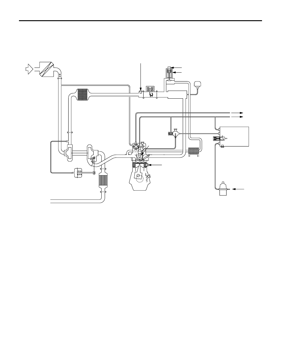
<Except Euro5>
AK500419
Waste gate
actuator
Catalytic
converter
EGR valve (DC motor)
Engine coolant
temperature sensor
Air
Injector
From fuel
tank
To fuel tank
To brake system
AB
Intake air temperature sensor No. 2
EGR valve position sensor