Mitsubishi L200. Manual - part 35


  Index      Mitsubishi     Mitsubishi L200 - service repair manual 2012 year


Search            


Content   ..  33  34  35  36   ..


Mitsubishi L200. Manual - part 35


ALTERNATOR

ENGINE OVERHAUL

11B-14

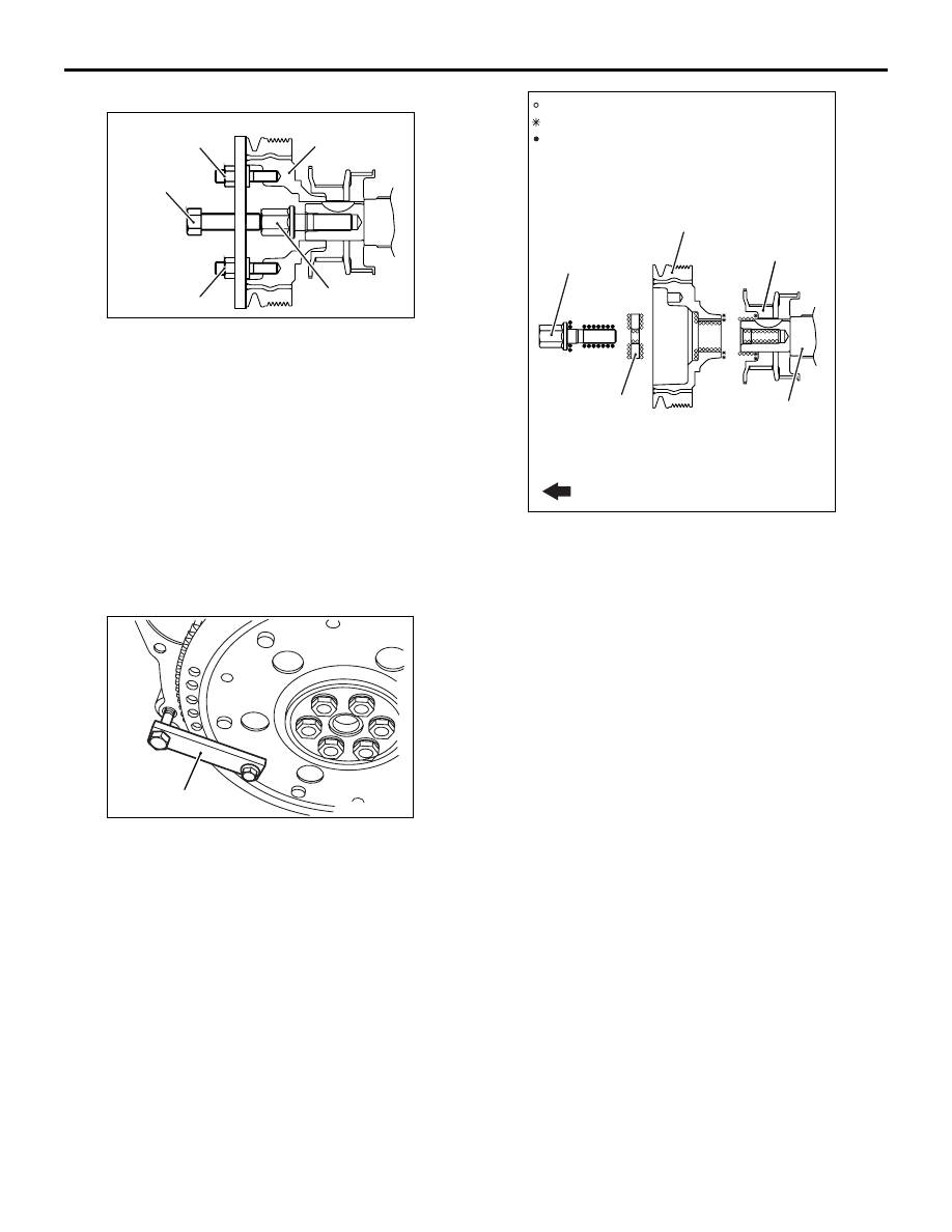
<<B>> CRANKSHAFT PULLEY REMOVAL

AK502851

Crankshaft
pulley

MB992099

AB

Crankshaft bolt

MB992100

MB992100

1. Screw securely the crankshaft bolt into the 

crankshaft.

2. Use the special tool, remove the crankshaft 

pulley.

• Crank pulley puller (MB992099)

• Crank pulley holder (MB992100)

3. Remove the crankshaft bolt.

INSTALLATION SERVICE POINTS

>>A<< CRANKSHAFT BOLT / CRANKSHAFT 
PULLEY WASHER / CRANKSHAFT PULLEY 
INSTALLATION

AK402854AB

MD998781

1. Use the special tool Flywheel stopper 

(MD998781), hold the flywheel.

AK603656

Crankshaft

Crankshaft pulley

Crankshaft bolt

AB

Crankshaft
pulley washer

Crankshaft sprocket

: Wipe clean with a rag.
: Wipe clean with a rag and degrease.
: Wipe clean with a rag, degrease and
  apply a small amount of engine oil.

Engine front

2. Wipe the dirt on the crankshaft pulley washer 

using a rag.

3. Using a rag, wipe the dirt on the crankshaft pulley, 

the crankshaft sprocket, the thread hole of the 
crankshaft and then remove the grease.
NOTE: Degreasing is necessary to prevent 
decrease in the friction between contacting sur-
faces.

4. Install the front flange and crankshaft pulley.
5. Apply an appropriate and minimum amount of 

engine oil to the threads of crankshaft bolt and 
lower part of the flange.

6. Install the crankshaft pulley washer to the 

crankshaft bolt.

7. Tighten the crankshaft bolt to the specified torque 

of 265 N

⋅m.

8. Loosen the bolt completely.
9. Tighten the crankshaft bolt again to the specified 

torque of 275 N

⋅m.

INLET MANIFOLD

ENGINE OVERHAUL

11B-15

INLET MANIFOLD

REMOVAL AND INSTALLATION

M1113026101258

<Except Euro5>

AK801103

3

4

13

8

14 ± 1 N·m

17 ± 2 N·m

24 ± 3 N·m

48 ± 6 N·m

11 ± 1 N·m

11

9

20 ± 4 N·m

2

14

15

16

17

18

19

20

10

5

6

7

AB

24 ± 3 N·m

24 ± 3 N·m

13 ± 2 N·m

49 ± 6 N·m

17 ± 2 N·m

20 ± 2 N·m

12

17 ± 2 N·m

1

Removal steps 

1.

Vacuum hose

2.

Vacuum pump pipe "B"

3.

Air temperature sensor

4.

Gasket

5.

EGR pipe "B"

6.

EGR pipe gasket

7.

EGR pipe gasket

8.

EGR pipe heat protector

9.

EGR pipe "A"

10. EGR pipe gasket

>>

D

<< 11. EGR pipe gasket

12. EGR valve

>>

C

<< 13. EGR valve gasket

14. Throttle body

>>

B

<< 15. Throttle body gasket

16. Fuel inlet pipe
17. Inlet manifold stay

>>

A

<< 18. Inlet manifold

19. Herical gasket
20. Tangential gasket

Removal steps (Continued)

INLET MANIFOLD

ENGINE OVERHAUL

11B-16

<Euro5>

AKB00325

3

13

9

14 ± 1 N·m

17 ± 2 N·m

24 ± 3 N·m

48 ± 6 N·m

11

20 ± 4 N·m

2

14

15

16

17

18

19

20

10

7

5

8

AB

24 ± 3 N·m

24 ± 3 N·m

13 ± 2 N·m

49 ± 6 N·m

17 ± 2 N·m

20 ± 2 N·m

12

17 ± 2 N·m

1

17 ± 2 N·m

6

4

Removal steps 

1.

Vacuum hose

2.

Vacuum pump pipe "B"

3.

Air temperature sensor

4.

EGR pipe fitting  "B"

5.

EGR pipe gasket

6.

EGR pipe gasket

7.

EGR pipe "B"

8.

EGR pipe gasket

9.

EGR pipe "A"

10. EGR pipe gasket

>>

D

<< 11. EGR pipe gasket

12. EGR valve

>>

C

<< 13. EGR valve gasket

14. Throttle body

>>

B

<< 15. Throttle body gasket

16. Fuel inlet pipe
17. Inlet manifold stay

>>

A

<< 18. Inlet manifold

19. Herical gasket
20. Tangential gasket

Removal steps (Continued)

INLET MANIFOLD

ENGINE OVERHAUL

11B-17

INSTALLATION SERVICE POINTS

>>A<< INLET MANIFOLD INSTALLATION

AK500701AB

A side

B side

1. As shown in the illustration, temporarily tighten to 

6.0 

± 1.0 N⋅m the bolts located at side "A."

2. As shown in the illustration, tighten to the 

specified torque of 24 

± 3 N⋅m the bolts located at 

side "B" Tighten nuts to the specified torque of 20 
± 2 N⋅m.

3. As shown in the illustration, tighten to the 

specified torque of 24 

± 3 N⋅m the bolts located at 

side "A."

>>B<< THROTTLE BODY GASKET 
INSTALLATION

AK500702

Projection

AB

Position the projection as shown in the illustration.

>>C<< EGR VALVE GASKET INSTALLATION

AK500703

Projection

AB

Position the projection as shown in the illustration.

>>D<< EGR PIPE GASKET INSTALLATION

AK500704AB

Projection

Position the projection as shown in the illustration.


Content   ..  33  34  35  36   ..