Mazda Protege 5. Manual - part 261


  Index      Mazda     Mazda Protege 5 - service repair manual 2002 year


Search            


Content   ..  259  260  261  262   ..


Mazda Protege 5. Manual - part 261


AUTOMATIC TRANSAXLE SHIFT MECHANISM 

05–18–6

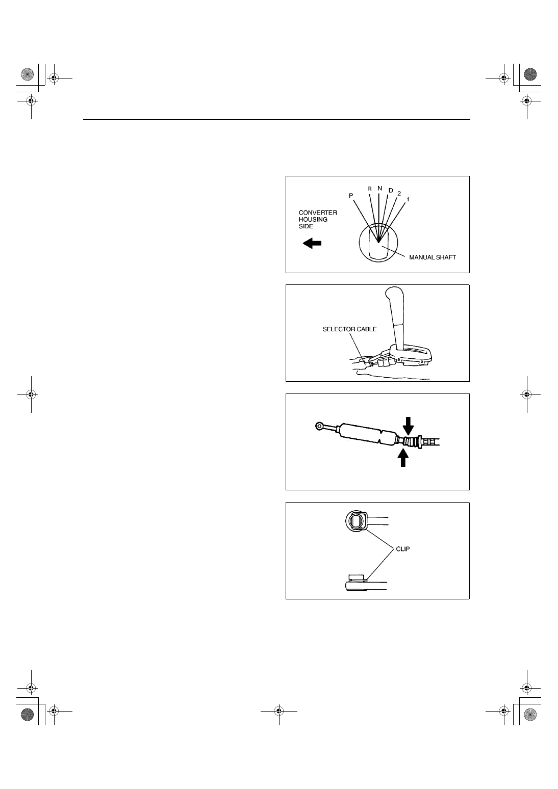
Selector Cable Installation Note

Caution

••••

Do not apply load to the manual shaft after manual shaft is shifted to P position. Otherwise, the 
transaxle may be damaged.

1. Turn the manual shaft to the converter housing 

side fully, to set the P position.

2. Install the selector cable to the selector lever.

Caution

••••

Bending the selector cable in the manner 
shown in the figure will damage the cable 
and it may become loose when shifted. 
When installing the selector cable, hold it 
straight.

3. Install the clip as shown in the figure.

X3U518WAD

X3U518WAE

X3U518WAF

X3U518WAQ

1712-1U-01G(05-18).fm  6 ページ  2001年6月29日 金曜日 午前10時14分

AUTOMATIC TRANSAXLE SHIFT MECHANISM 

05–18–7

05–18

Note

Install the selector cable to the manual shaft 
lever with the spring side of the selector 
cable end facing the front of the vehicle.

4. Install the selector cable to the manual shaft lever 

in such a way that the selector cable does not 
bear a load.

5. Confirm that the end of the manual shaft lever 

sticks out of the end of the selector cable.

6. Install the selector cable to the cable bracket.
7. Verify that the selector lever is at P position.

8. Unlock the lock piece of the selector cable 

(selector lever side) in the order shown in the 
figure.

9. Shift the selector lever from P position to 1 range, 

and make sure that there are no other 
components in that area to interfere with the 
lever.

End Of Sie

X3U518WAG

X3U518WAH

X3U518WAJ

1712-1U-01G(05-18).fm  7 ページ  2001年6月29日 金曜日 午前10時14分

AUTOMATIC TRANSAXLE SHIFT MECHANISM 

05–18–8

SELECTOR LEVER DISASSEMBLY/ASSEMBLY

A3U051846102W04

1. Disassemble in the order indicated in the table.
2. Assemble in the reverse order of disassembly.

.

Connector Disassembly Note

1. Insert a thin piece of metal from the terminal side 

of the connector, and press down the terminal 
locking tab.

2. Pull the terminal out of the connector.

X3U518WAK

1

Connector
(See 05–18–8 Connector Disassembly Note.)

2

Screw

3

Selector lever knob

4

Cover

5

Indicator panel

6

Selector illumination light

7

Cam
(See 05–18–9 Cam Assembly Note.)

8

Selector lever

X3U518WAL

1712-1U-01G(05-18).fm  8 ページ  2001年6月29日 金曜日 午前10時14分

AUTOMATIC TRANSAXLE SHIFT MECHANISM 

05–18–9

05–18

Cam Assembly Note

1. Loosely install the cam to the push rod.

Note

Clearance can be reduced by turning the cam clockwise.

2. Adjust the clearance between the guide plate and 

the guide pin by turning the cam.

3. Install the selector lever knob and verify that the 

clearance is as specified.

If not, repeat from Step 2.

4. Remove the selector lever knob.

5. Apply grease to the cam as shown.

End Of Sie

X3U518WAM

X3U518WAN

1712-1U-01G(05-18).fm  9 ページ  2001年6月29日 金曜日 午前10時14分


Content   ..  259  260  261  262   ..