Mazda Protege 5. Manual - part 259


  Index      Mazda     Mazda Protege 5 - service repair manual 2002 year


Search            


Content   ..  257  258  259  260   ..


Mazda Protege 5. Manual - part 259


AUTOMATIC TRANSAXLE 

05–17–45

05–17

Radiator Installation Note

1. The ATX oil cooler flushing must be performed whenever a transaxle is removed for service because the 

existing fluid may be contaminated, and to prevent contamination of new fluid. The flushing must be performed 
after installation of the overhauled or replaced transaxle. (See 05–17–40 OIL COOLER FLUSHING)

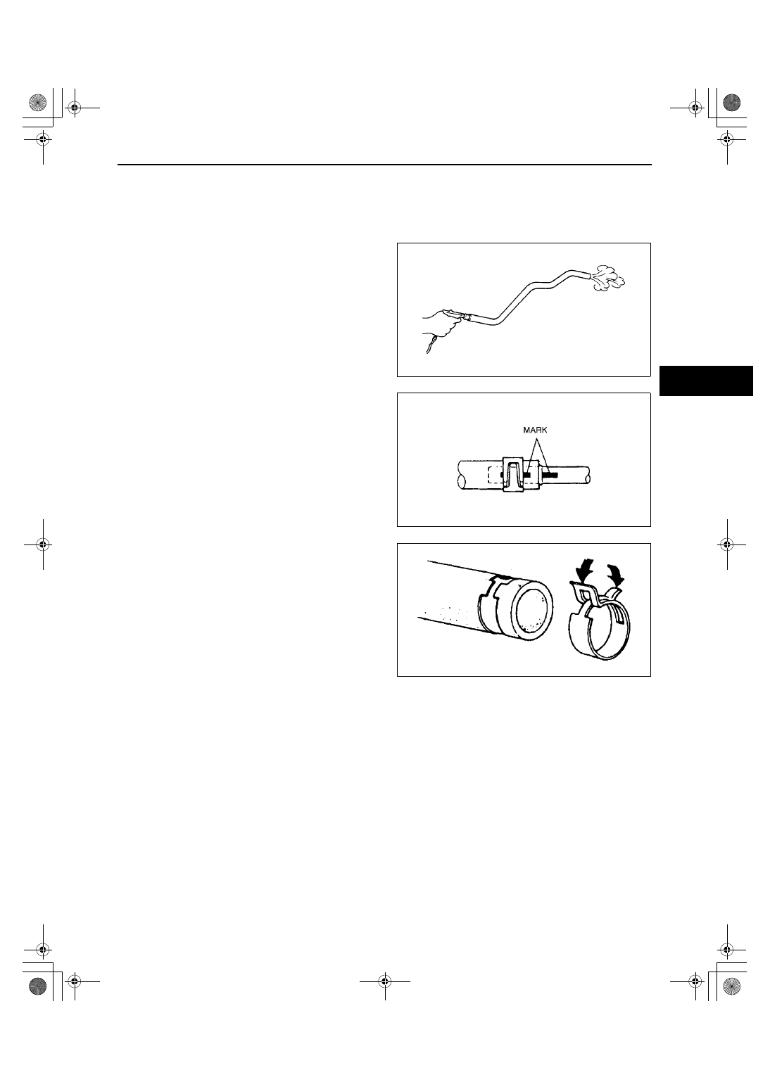
Oil Hose Installation Note

1. Apply compressed air to cooler-side opening 

more than 1 minute, and blow any remaining 
grime and foreign material from the cooler pipes.

2. Align the marks, and slide the oil hose onto the oil 

pipe until it is fully seated as shown.

3. Install the hose clamp onto the hose.

If reusing the hose, install a new hose clamp 
exactly on the mark left by the previous hose 
clamp.

4. Verify that the hose clamp does not interfere with 

any other components.

End Of Sie

X3U517WC1

Y3U517WAN

X3U517WC3

1712-1U-01G(05-17).fm  45 ページ  2001年6月29日 金曜日 午前10時12分

AUTOMATIC TRANSAXLE 

05–17–46

DRIVE PLATE REMOVAL/INSTALLATION

A3U051719020W01

1. Remove the transaxle. (See 05–17–31 

AUTOMATIC TRANSAXLE (ATX) REMOVAL/
INSTALLATION.)

2. Remove in the order indicated in the table.
3. Install in the reverse order of removal.
4. Install the transaxle. (See 05–17–31 

AUTOMATIC TRANSAXLE (ATX) REMOVAL/
INSTALLATION.)

Drive Plate Mounting Bolts Removal Note

1. Set the SST or equivalent against the drive plate.
2. Remove the drive plate mounting bolts.

Drive Plate Mounting Bolts Installation Note

Caution

••••

If the bolts are reused, remove the oil sealant from the bolt threads. Tightening a bolt that has old 
sealant on it can cause thread damage.

1. Remove the sealant from the bolts hole in the crankshaft and from the drive plate mounting bolts.

Note

If all the previous sealant cannot be removed from a bolt, replace the bolts.

Do not apply sealant if new bolts are used.

2. Install the drive plate.
3. Install the adapter.
4. Apply sealant to the drive plate mounting bolts and install them.
5. Set the SST or equivalent against the drive plate.

Caution

••••

When installing sealant covered bolts tighten them immediately. Leaving these bolts in a half 
installed condition could cause them to be stuck that way, due to the natural hardening of the 
sealant.

1

Drive plate mounting bolt
(See 05–17–46 Drive Plate Mounting Bolts Removal 
Note.)
(See 05–17–46 Drive Plate Mounting Bolts 
Installation Note.)

2

Washer

3

Adapter

4

Drive plate

X3U517WCD

X3U517WCE

1712-1U-01G(05-17).fm  46 ページ  2001年6月29日 金曜日 午前10時12分

AUTOMATIC TRANSAXLE 

05–17–47

05–17

6. Tighten the drive plate installation bolts in 2 or 3 

steps as shown.

Tightening torque

97—102 N·m {9.8—10.5 kgf·m,70.9—75.9 

ft·lbf}

End Of Sie

X3U517WCF

1712-1U-01G(05-17).fm  47 ページ  2001年6月29日 金曜日 午前10時12分

AUTOMATIC TRANSAXLE SHIFT MECHANISM 

05–18–1

05–18

05–18

AUTOMATIC TRANSAXLE SHIFT MECHANISM

AUTOMATIC TRANSMISSION SHIFT 

MECHANISM LOCATION INDEX . . . . .  05–18–1

INTERLOCK CABLE INSPECTION . . . .  05–18–1
SELECTOR LEVER INSPECTION . . . . .  05–18–2
SELECTOR LEVER ADJUSTMENT . . . .  05–18–2
SELECTOR LEVER 

REMOVAL/INSTALLATION . . . . . . . . .  05–18–3

Selector Cable Removal Note . . . . . . .  05–18–4

Interlock Cable and Lock Unit 

Installation Note  . . . . . . . . . . . . . . . . . 05–18–4

Selector Cable Installation Note  . . . . . . 05–18–6

SELECTOR LEVER 

DISASSEMBLY/ASSEMBLY . . . . . . . . . 05–18–8

Connector Disassembly Note . . . . . . . . 05–18–8
Cam Assembly Note . . . . . . . . . . . . . . . 05–18–9

End of Toc

AUTOMATIC TRANSMISSION SHIFT MECHANISM LOCATION INDEX

A3U051864350W01

.

End Of Sie

INTERLOCK CABLE INSPECTION

A3U051846300W01

1. Remove the interlock cable and lock unit. (See 05–18–3 SELECTOR LEVER REMOVAL/INSTALLATION.)

If the slider pin protrusion is as specified below (dimension A), verify that the interlock cable moves freely in 
the lock unit.

If not as specified, replace the interlock cable.

2. Install the interlock cable and lock unit. (See 05–

18–4 Interlock Cable and Lock Unit Installation 
Note.)

End Of Sie

Z3U518W01

1

Interlock cable
(See 05–18–1 INTERLOCK CABLE INSPECTION)

2

Selector  lever
(See 05–18–3 SELECTOR LEVER REMOVAL/
INSTALLATION)
(See 05–18–2 SELECTOR LEVER INSPECTION)
(See 05–18–2 SELECTOR LEVER ADJUSTMENT)
(See 05–18–8 SELECTOR LEVER DISASSEMBLY/
ASSEMBLY)

X3U518WA0

1712-1U-01G(05-18).fm  1 ページ  2001年6月29日 金曜日 午前10時14分


Content   ..  257  258  259  260   ..