Mazda Protege 5. Manual - part 128
MECHANICAL [FS]
01–10B–19
01–10B
FRONT OIL SEAL REPLACEMENT [FS]
A3U011010602W01
1. Disconnect the negative battery cable.
2. Remove the timing belt. (See 01–10B–8 TIMING BELT REMOVAL/INSTALLATION [FS].)
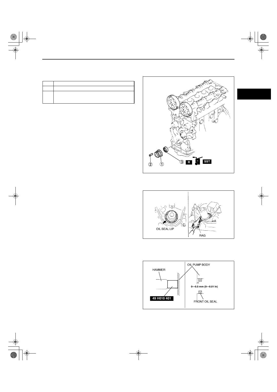
3. Remove in the order indicated in the table.
4. Install in the reverse order of removal.
Front Oil Seal Removal Note
1. Cut the oil seal lip using a razor.
2. Remove the oil seal using a screwdriver protected
with a rag.
Front Oil Seal Installation Note
1. Apply clean engine oil to the oil seal lip.
2. Push the oil seal slightly in by hand.
3. Tap the oil seal in evenly using the SST and a
hammer.
End Of Sie
1
Timing belt pulley
2
Key
3
Front oil seal
(See 01–10B–19 Front Oil Seal Removal Note)
(See 01–10B–19 Front Oil Seal Installation Note)
X3U110WGB
X3U110WGC
Y3U110WA8
1712-1U-01G(01-10B).fm 19 ページ 2001年6月29日 金曜日 午前9時39分